
Operator's Manual

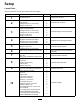

ProcedureDescription
Qty.
Use
Bumper2
Spacer
2
11
Locknut(5/16inch)
2
Installthebumpers(formachineswith
MyRide™suspensionsystem).
12
Nopartsrequired
–
Adjusttheparkingbrake.
13
Nopartsrequired
–
Checkthetirepressure.
Note:Determinetheleftandrightsidesofthemachinefromthenormaloperatingposition.
1
PreparingtheMachine
NoPartsRequired
Procedure
Performthefollowingproceduretopreparethe
machineforattachingtheblowerandnishingkit.
1.DisengagethePTO,movethemotion-control
leverstotheNEUTRAL-LOCKEDposition,and
engagetheparkingbrake.
2.Shutofftheengine,removethekey,andwait
forallmovingpartstostopbeforeleavingthe
operatingposition.
3.Repairallbentordamagedareasofmachine
deckandreplaceanymissingparts.
4.Cleanthemachineofanydebrisonthemachine
deckorrearpartofthemachinetoease
installation.
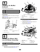
2
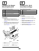
InstallingtheSideBumpers
Partsneededforthisprocedure:
1
Leftbumper
1Rightbumper
2
Carriagebolt(3/8x1-1/4inches)
6
Flangenut(3/8inch)
Procedure
1.Removethenutsandboltsholdingtheside
bumperstothemachine(Figure4).
Note:Discardallnutsandonlythe1bolt
removedfromeachside.
2.Installthenewleftandrightsidebumperswith2
carriagebolts(3/8x1-1/4inches),4previously
removedcarriagebolts,and6angenuts(3/8
inch)asshowninFigure4.
g009214
Figure4
1.Flangenut(3/8inch)4.Leftbumper
2.Rightbumper
5.Bolt(3/8x1-1/4inches)
3.Useexistingbolts
6