Form No. 3438-500 Rev A 48in, 52in, 60in, or 72in E-Z Vac™ DFS Collection System Z Master® G3 Mower Model No. 78556—Serial No. 400000000 and Up Model No. 78566—Serial No. 405700000 and Up Model No. 78567—Serial No. 405700000 and Up Register at www.Toro.com.
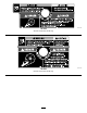
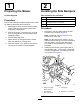
Introduction Read this information carefully to learn how to operate and maintain your product properly and to avoid injury and product damage. You are responsible for operating the product properly and safely. g009233 You may contact Toro directly at www.Toro.com for product safety and operation training materials, accessory information, help finding a dealer, or to register your product. Figure 2 48- and 52-inch bagger serial number 1.
Contents Adjusting the Open Door for 48- and 52-inch Mowers ......................................................... 37 Adjusting the Parking Brake.............................. 39 Inspecting the Mower Blades ............................ 39 Installing the Mower Blades .............................. 39 Installing the Grass Deflector ............................ 39 Storage ................................................................... 40 Troubleshooting .................................................
Safety the manufacturer's recommended parts, when necessary. The following list contains safety information specific to Toro products and other safety information you must know. Towing Safety • Do not attach towed equipment except at the hitch • Become familiar with the safe operation of the point. equipment, with the operator controls, and safety signs. • Follow the attachment manufacturer's recommendation for weight limits for towed equipment and towing on slopes.
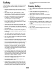
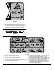
Safety and Instructional Decals Safety decals and instructions are easily visible to the operator and are located near any area of potential danger. Replace any decal that is damaged or lost. decal1-653554 1-653554 decal106-3339 106-3339 decal1-653558 1-653558 decal126-4659 126-4659 1. Warning—hot pulley; allow to cool. decal98-5954 98-5954 decal126-9451 126-9451 1. Thrown objects hazard—Do not run the blower without the entire collection system installed and latched. decal106-5517 106-5517 2.
decal126-9595 126-9595 1. Rotation indicator 2. Impeller/Rotating Blades hazard-Keep hands away from moving parts. Keep all safety devices in place and working. Do not reach into the blower unless the rotation indicator has stopped. Disengage the PTO, shut off the engine, remove the key, and wait for all moving parts to stop. decal133-8061 133-8061 decal136-4164 136-4164 1. Warning—read the Operator’s Manual. 4.
decal103-3508 103-3508 48-inch and 52-inch decks only decal109-5890 109-5890 60-inch and 72-inch decks only 7
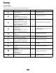
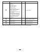
Setup Loose Parts Use the chart below to verify that all parts have been shipped. Procedure 1 2 3 4 5 6 7 8 9 10 11 Description Qty.
Procedure 12 13 14 15 Description Qty.
1 2 Preparing the Mower Installing the Side Bumpers No Parts Required Parts needed for this procedure: 1 Left bumper Procedure 1 Right bumper Perform the following procedure to prepare the mower for attaching the blower and finishing kit. 2 Carriage bolt (3/8 x 1-1/4 inches) 6 Flange nut (large flange–3/8 inch) 1. 2. Disengage the PTO, move the motion-control levers to the NEUTRAL-LOCKED position and engage the parking brake. Procedure 1.
2. 3 Installing the Bagger Mounting Brackets 4 Parts needed for this procedure: 1 Upper mounting bracket 1 Lower mounting bracket 4 Carriage bolt (3/8 x 1-1/4 inches) 2 Carriage bolt (1/2 x 2–1/2 inches) 4 Flange nut (large flange–3/8 inch) 2 Flange nut (1/2 inch) Installing the Handle Assembly and Bracket 60- and 72-inch Mowers Parts needed for this procedure: Procedure Note: For 60- and 72-inch mowers, do not install the bolt and flange nut for the left side of the lower mounting bracket.
3. Install the handle and bracket assembly to the side of the machine with 3 carriage bolts (3/8 x 1-1/4 inches) and 3 flange nuts (large flange–3/8 inch) as shown in Figure 8. 5 Installing the Handle Assembly and Bracket for 48- and 52-inch Mowers Note: Ensure that the bolts go through the left bumper and the lower bagger bracket and connect them to the side of the machine.
6 Installing the Bagger Assembly Parts needed for this procedure: 1 Bagger assembly 2 Pin and hairpin cotter assembly Procedure 1. Position the bagger on its back (Figure 10). 2. Slide the hooks onto the lower mounting bracket (Figure 10). 3. Rotate the bagger up on the lower bagger mounting bracket. 4. Align the hole in the bagger with the upper mounting bracket (Figure 10). 5. Install the pin and secure it with the hairpin cotter on both sides (Figure 10). g009219 Figure 10 1.
7 Installing the Muffler Deflector Parts needed for this procedure: 1 Muffler deflector 2 Flange nut (small flange–3/8 inch) 2 Carriage bolt (3/8 x 1-1/4 inches) g009218 Figure 11 1. Bagger-arm assembly 3. Clevis-pin spring 2. Bagger-handle linkage 4. Yoke Procedure Install the muffler deflector to the side of the bagger frame (Figure 12). Note: Ensure that the muffler deflector is positioned over the tail pipe on the muffler. g009221 Figure 12 60- and 72-inch bagger shown 1.
8 Routing the Blower Belt into the Blower Assembly Parts needed for this procedure: 1 Blower belt (from the Blower and Drive Kit) Procedure 1. g010508 For 60- and 72-inch mowers, install the belt around the blower pulley (Figure 13). Figure 14 Blower for 48- and 52-inch mowers g003398 Figure 13 Blower for 60- and 72-inch Mowers 1. Idler pulley 4. Peg 2. Mower-deck pulley 5. Belt 3. Spring 6. Blower pulley 2. For 48- and 52-inch mowers, loosen the belt guide (Figure 14). 3.
9 Installing the Blower Assembly Parts needed for this procedure: 1 Blower assembly (from the Blower and Drive Kit) 1 Spring (from the Blower and Drive Kit) g002519 Figure 15 Procedure WARNING An uncovered discharge opening could allow the lawn mower to throw objects at you or bystanders, resulting in serious injury. Also, contact with the blade could occur. • Never operate the lawn mower unless you install a cover plate, a mulch plate, or a grass chute and catcher.
2. Slide the blower-assembly peg into the pivot hole (Figure 16 or Figure 17). 3. Close the blower assembly to see if the latches are adjusted correctly (Figure 18). Note: Loosen or tighten the bolt so the latches firmly hold the blower assembly against the mower deck but can be released by hand g009420 Figure 16 48- and 52-inch mower deck shown 1. Blower assembly 3. Pivot hole 2. Mower deck 4. Blower-assembly peg g003400 Figure 18 1. Latch 3. Blower assembly 2. Bolt 4.
5. Pull the spring-loaded idler pulley back and route the belt around the mower-deck pulley (Figure 20). 10 Note: Ensure that the belt is routed around the Installing the Discharge Tubes blower pulleys correctly Parts needed for this procedure: 1 Upper tube 1 Lower tube 3 Bolt (#10 x 3/4 inches) 3 Locknut (#10) 3 Washer (7/32 inch) Procedure g003399 Important: Make sure that the mower deck is in Figure 20 1.
Note: Measure from the hood plate to the edge of the tube as shown in Figure 22. This distance needs to be 19 mm (3/4 inch). g003393 Figure 23 1. Upper tube 3. Bagger hood 2. Rubber seal protruding out 4. Mark here against the rubber seal. g003388 Figure 22 1. Hood plate 4. 3/4 inch (19 mm) 2. Upper tube 5. Edge of tube 3. Hood in the down position 6. Once the 19 mm (3/4 inch) measurement has been achieved, mark the upper tube on the outside where the rubber seal protrudes out (Figure 23).
7. Install the lower tube into the upper tube (Figure 24). g003424 Figure 24 1. Lower tube 8. 2. Upper tube Slide the lower tube onto the boot and latch them together (Figure 25 or Figure 26). g030596 Figure 25 1. Blower assembly Note: There is a latch on the top and bottom 2. Lower tube of the blower housing. Note: Make sure that the mower deck is in the lowest height-of-cut position and the mark on the upper tube is still positioned against the protruding rubber seal.
9. Using the 3 holes or indentations in the upper tube as a template, drill 3 holes (7/32 inch diameter) where the upper and lower tubes join together (Figure 27). g003423 Figure 26 60- and 72-inch bagger shown g003390 Figure 27 1. Blower assembly 3. Latch 2. Lower tube 1. Bagger hood 4. Lower tube 2. Upper tube 5. Blower assembly 3. Drill 7/32 inch diameter holes here (use the upper tube as a template) 10. 21 Remove the lower tube from the blower.
11. Join the upper and lower tubes with 3 bolts (#10 x 3/4 inches), 3 flat washers (7/32 inch), and 3 locknuts (#10) as shown in Figure 28. g009305 Figure 29 48- and 52-inch bagger shown 1. Belt cover 2. Belt-cover support 3. Notch g003392 Figure 28 1. Lower tube 4. Locknut (#10) 2. Upper tube 5. Bolt, (#10 x 3/4 inches) 3. Flat washer (7/32 inch) 12. Install the lower tube onto the blower housing and secure it with the latches.
12 Installing the Weights Parts needed for this procedure: 2 Caster weight (if needed) 2 Clevis pin 2 Hairpin cotter 6 Lock washer (3/8 inch) 1 Weight-mount bracket 6 Bolt (3/8 x 1 inch) 6 Flat washer (3/8 inch) 3 Flange nut (small flange–3/8 inch) 2 Carriage bolt (5/16 x 3/4 inch) 2 Flange nut (5/16 inch) 3 Front weight (48-inch, 52-inch, and 60-inch decks) 1 Front weight [72-inch decks (serial number 406294344 and below)] 2 Front weight [72-inch decks (serial number 406294345 and
6. Secure the front weights on top of the foot rest and to the weight-mount bracket with 6 bolts (3/8 x 1 inch), 6 lock washers (3/8 inch), 3 flange nuts (small flange) (3/8 inch) and 6 flat washers (3/8 inch) (Figure 33). g009226 Figure 32 1. Carriage bolt (5/16 x 3/4 inch) 3. Flange nut (5/16 inch) 2. Weight-mount bracket 5. Install the front weights on top of the foot rest (Figure 33). g009227 Figure 33 1. Front weight 4. Bolt (3/8 x 1 inch) 2. Flat washer (3/8 inch) 5. Hole in footrest 3.
For 72-inch decks (serial number 406294344 and below), install the bumpers to the 2 inside holes of the toeboard (Figure 36). 13 Installing the Bumpers Machines with MyRide™ Suspension System Parts needed for this procedure: 2 Bumper 2 Spacer 2 Locknut (5/16 inch) Procedure For 48-inch, 52-inch, 60-inch, and 72-inch decks (serial number 406294345 and above), install the bumpers to the 2 outside holes of the toeboard (Figure 35). g030507 Figure 36 1. Locknut (5/16 inch) 3. Bumper 2.
Operation 15 Note: Determine the left and right sides of the machine from the normal operating position. Checking the Tire Pressure Important: Set the parking brake when you leave the machine, even if just for a few minutes. No Parts Required WARNING Procedure To avoid personal injury, follow these procedures: Note: Increase the tire pressure due to the additional • Become familiar with all operating and safety instructions in the Operator's Manual for your machine before using this attachment.
WARNING Without the grass deflector, bagger tubes or complete collection system mounted in place, you and others are exposed to blade contact and thrown debris. Contact with the rotating mower blade(s) and thrown debris will cause injury or death. • Always install the grass deflector when you remove the collection system and change to side-discharge mode. • If the grass deflector is ever damaged, replace it immediately. The grass deflector routes material down toward the turf.
Emptying the Bagger 6. 1. Disengage the PTO and set the parking brake. 2. Lift the handle to open the door and empty the hopper. 3. Use a stick or similar object, not your hands, to remove and clear the obstruction from the tube assembly. Note: In most cases, the debris can be shaken out of the tubes. Push the handle down to close the door (Figure 39). 7.
Using the Grass Deflector is less. Cutting off more than this will reduce the capacity of the vacuum system. DANGER Cutting Frequency Without the grass deflector, discharge cover, or complete grass catcher assembly mounted in place, you and others are exposed to blade contact and thrown debris. Contact with rotating mower blade(s) and thrown debris will cause injury or death. • Always install the grass deflector when removing the collection system and changing to side discharge mode.
Reducing Plugging To avoid plugging the bagging system, reduce the ground speed and mow the grass at a high height-of-cut, then lower the mower to your normal cutting height and repeat the bagging process. Signs of Plugging As you use the bagger, a small amount of grass clippings normally blow out the front of the mower. An excessive amount of clipping blow-out indicates that the bagger is full or the tube is plugged.
Maintenance Recommended Maintenance Schedule(s) Maintenance Service Interval Maintenance Procedure After the first 8 hours • Inspect the blower belt. • Inspect the collection system. After the first 100 hours • Adjust the parking brake (also when replacing or removing a brake component). Before each use or daily • Clean the hood screen. • Clean the collection system. Every 25 hours • Inspect the blower belt. Every 50 hours • Grease the idler arm. Every 100 hours • Grease the handle pivot.
Inspecting the Blower Belt 6. Install the spring as shown in Figure 41. Service Interval: After the first 8 hours Every 25 hours Check the belts for cracks, frayed edges, burn marks, or any other damage. Replace damaged belts. Replacing the Blower Belt for 60- and 72-inch Mowers 1. Disengage the PTO, move the motion-control levers to the NEUTRAL-LOCKED position, and set the parking brake. 2. Stop the engine, remove the key, and wait for all moving parts to stop before leaving the operating position.
Checking and Adjusting the Blower Latch Close the blower assembly to see if the latches are adjusted correctly. Loosen or tighten the bolts so the latches firmly hold the blower assembly against the mower deck but can be released by hand. g003454 Figure 42 1. Idler pulley 5. Belt 2. Mower-deck pulley 6. Belt-guide bolt 3. Spring 7. Fixed-idler pulley 4. Spring peg 8. Blower pulley g003400 Figure 44 1. Latch 3. Blower assembly 2. Bolt 8. Install the spring as shown in Figure 43.
Adjusting the Closed Door for 60- and 72-inch Mowers For 60-and 72-inch mowers only, grease the handle pivot (Figure 46). 1. Disengage the PTO, move the motion-control levers to the NEUTRAL-LOCKED position, and set the parking brake. 2. Stop the engine, remove the key, and wait for all moving parts to stop before leaving the operating position. 3. With the door closed, loosen the nuts and adjust the stop bolts so that the contact arm is straight up and down (Figure 47). 4.
Adjusting the Open Door for 60- and 72-inch Mowers Adjusting the Latches for 60- and 72-inch Mowers Note: Perform this procedure after adjusting the door Note: Adjust the open door and closed door positions before adjusting the latches. to completely close. Adjust the handle link to so that the door opens as much as possible(Figure 48 and Figure 49). Note: Lengthen the handle link to open the door farther.
g007380 g007381 Figure 51 1. Bolt Figure 52 3. Side plate 1. Right bellcrank arm 2. Washer 4. Check the distance between the left and right bellcranks and the upper frame tube. 2. Allen-head bolt Note: These dimensions need to be the same on both sides. 5. To make the distances equal, loosen the Allen-head bolt on the hub of the right bellcrank (Figure 52). 6. Position the bellcrank arms the same distance from the upper frame tube. 7. Tighten the Allen-head bolt and install the side plates.
Adjusting the Open Door for 48- and 52-inch Mowers Perform this after adjusting the closed door. 1. Remove the side plate from both sides of the bagger (Figure 54). g007383 Figure 53 1. Door 2. Hinge link 3. Nut g007380 Figure 54 1. Bolt 2. Washer 2. 37 Open the door. 3.
3. Check the distance between the upper tube of the door frame and the lower lip of the molded hood (Figure 55). Note: The distance should be between 3.2 mm (1/8 inch) and 9.6 mm (3/8 inch). g007382 Figure 56 1. Hinge stop g007379 Figure 55 1. Lower lip of the molded hood 2. The measurement is between an 3.2 mm (1/8 inch) and 9.6 mm (3/8 inch). 4. 3.
Adjusting the Parking Brake Installing the Grass Deflector Service Interval: After the first 100 hours WARNING Refer to the Operator’s Manual for the machine to adjust the parking brake. An uncovered discharge opening could allow the lawn mower to throw objects at you or others and result in serious injury. Also, contact with the blade could occur. Inspecting the Mower Blades 1. Inspect the mower blades regularly and whenever a blade strikes a foreign object. 2.
Storage g002519 Figure 57 1. Bolt 5. Spring installed 2. Spacer 6. Grass Deflector 3. Locknut 7. L end of spring, place behind deck edge before installing bolt 4. Spring 8. J-hook end of spring 40 1. Clean the bagger. Refer to Cleaning the Bagger Screen (page 31) and Cleaning the Collection System (page 31). 2. Inspect the bagger for damage. Refer to Inspecting the Collection System (page 34). 3. Make sure that the bagger is empty and thoroughly dry. 4. Check the belt for wear or cracks.
Troubleshooting Problem There is abnormal vibration. Bagging performance is reduced. Blower and tubes plug too frequently. Possible Cause 1. Cutting blade(s) is/are bent or unbalanced. 1. Install new cutting blade(s). 2. A blade-mounting bolt is loose. 3. A blower pulley or pulley assembly is loose. 4. A blower belt is worn. 5. Blower fan blade(s) is/are bent or unbalanced. 2. Tighten the blade-mounting bolt. 3. Tighten the appropriate pulley. 1. The engine speed is low. 1.
Notes:
Notes: