
Setup Instructions

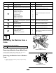


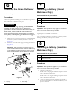


Figure19
1.Bolt(3/8x1inch)3.Controllever
2.Handle
4.Nut(3/8inch)
3.Raisetheleversandalignthemtogetherintheneutral
positionandtightenthebolts.
Figure20
Note:Ifthemachineisnotproperlytracking,referto
AdjustingtheTrackinginyourOperator'sManual.
13
InstallingtheLift-AssistPedal
(InternationalMachinesUsing
GasolineOnly)
Partsneededforthisprocedure:
1
Carriagebolt(3/8x1-1/2inches)
1
Flangelocknut(3/8inch)
Procedure
1.Ifneeded,loosentheexistingboltandnutforthe
lift-assistpedal.
2.Rotatethelift-assistpedaltothecorrectposition
andinstallthecarriagebolt(3/8x1-1/2inches)and
locknut(3/8inch)(Figure21).Tightenbothbolts.
1 2
3
g016346
Figure21
1.Lift-assistpedal3.Carriagebolt(3/8x1-1/2
inches)
2.Flangelocknut(3/8inch)
9