
Use and Care Manual

1
2
g030497
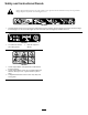
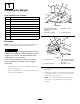
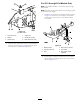
Figure16
1.Self-tappingscrew(5/16x
3/4inch)
2.Pivotframe
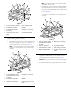
3.Attachthedraw-bardecal1.3cm(1/2inch)totheleft
oftheattachmentmount(Figure17)
g030498
1
Figure17
1.Drawbardecal
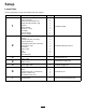
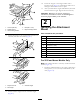
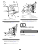
4.Installabent,aredendofarodintothekeyedslotin
theleftsideofthemachineframe,andmovetherod
rearwardtoseatitintheframe(Figure18).
Note:Repeatthisstepfortherightsideofthe
machine.
g030499
1
2
3
4
6 5
Figure18
Leftsideshown
1.Pivot-framehole4.Supportrod
2.Washer
5.Keyedslot(existing)
3.Hairpincotter
6.Bent,aredendofsupport
rod
5.Insertthebentendsoftherodintotheattachment
mountasshowninFigure18andsecuretheendof
eachrodwithawasherandhairpincotter.
3
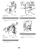
InstallingtheLatchRod
Partsneededforthisprocedure:
1Latchrod
1Hairpincotter
Procedure
Installthelatchrodwithahairpincotter(Figure19).
10