
Use and Care Manual

g030494
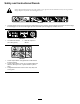
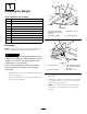
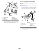
Figure10
2015modelshown
1.Stabilizerbracket3.Locknut(5/16inch)
2.Carriagebolt(5/16x3/4
inch)
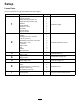
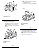
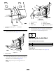
2.Installthepivotframetothemachineframeasshown
inFigure11.Securethepivotframetothemachine
frameusing2bolts(5/16x1inch)and2locknuts
(5/16inch).
Figure11
1.Machineframe4.Bolt(5/16x2-1/2inch)
2.Locknut(5/16inch)5.Pivotframe
3.Hole
3.Securethepivotframetothebottomofthemachine
frameusing2self-tappingscrews(5/16x3/4inch)as
showninFigure12.
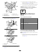
Figure12
1.Self-tappingscrew(5/16x
3/4inch)
2.Pivotframe
4.Attachthedrawbardecal1.3cm(1/2inch)totheleft
oftheattachmentmount(Figure13).
Figure13
1.Drawbardecal
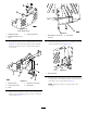
5.Installthebent,aredendofarodintothekeyedslot
intheleftsideofthemachineframe,andmovetherod
rearwardtoseatitintheframe(Figure14).
Note:Repeatthisstepfortherightsideofthe
machine.
8