
Use and Care Manual
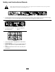
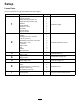
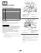
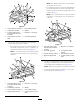
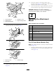
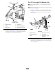
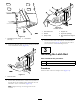

Figure14
Leftsideshown
1.Pivotframehole4.Supportrod
2.Washer5.Keyedslot,existing
3.Hairpincotter
6.Bent,aredendofrod
6.Insertthebentendsoftherodsintotheattachment
mountasshowninFigure14andsecuretheendof
eachrodwithawasherandhairpincotter.
For2011through2014ModelsOnly
Note:Thestabilizerbracketisnotusedon2011through
2014models.
Note:For2011through2014models,therear-engineguard
isoptionalforthisbagger.
1.Installthepivotframetothemachineframeasshown
inFigure15.Securethepivotframetothemachine
frameusing2bolts(5/16x1inch)and2locknuts
(5/16inch).
1
2
3
4
5
g032814
6
Figure15
1.Machineframe4.Bolt(5/16x2-1/2inch)
2.Locknut(5/16inch)5.Pivotframe
3.Hole6.Rear-engineguard
(optional)
2.Securethepivotframetothebottomofthemachine
frameusing2self-tappingscrews(5/16x3/4inch)as
showninFigure16.
9