Form No. 3329–246 Quiet Collector Wheel Horse 5xi Garden Tractor Attachment Model No. 79451—Serial No.
Contents Introduction . . . . . . . . . . . . . . . . . . . . . . . . . . . . . . . . Safety . . . . . . . . . . . . . . . . . . . . . . . . . . . . . . . . . . . . . Safety and Instruction Decals . . . . . . . . . . . . . . . . Setup . . . . . . . . . . . . . . . . . . . . . . . . . . . . . . . . . . . . . Loose Parts . . . . . . . . . . . . . . . . . . . . . . . . . . . . . . Installing the Quiet Collector Drive Kit . . . . . . . . Remove the Drawbar Hitch . . . . . . . . . . . . . . . . .
Safety The following list contains safety information specific to Toro products and other safety information you must know. • Become familiar with the safe operation of the equipment ant with the operator controls, and safety signs. • Use extra care with grass catchers or other attachments. These can change the operating characteristics and the stability of the machine. • Follow the manufacturer’s recommendations for adding or removing wheel weights or counterweights to improve stability.
Safety and Instruction Decals Safety decals and instructions are easily visible to the operator and are located near any area of potential danger. Replace any decal that is damaged or lost. 98-3679 1. Squeeze the lever. 2. Raise the handle to the dump position. 3. Release the lever. 4. Lower the handle to dump the grass clippings. 5. Return the handle to the dump position. 6. Squeeze the lever and lower the handle to the operation position. 7. Release the lever. 98-3680 1. Blow right 2. Collect grass 3.
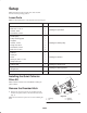
Setup Note: Determine the left and right sides of the machine from the normal operating position. Loose Parts Note: Use the chart below to verify all parts have been shipped. DESCRIPTION QTY. Quick hitch 1 Bolt, 3/8 x 1–1/4 in. 2 Locknut, 3/8 in. 2 Flat washer, 7/16 in. 4 Double pulley 1 Pulley mounting plate 1 Top plate 1 Locknut, 7/16 in. 1 Flange nut, 3/8 in. 4 Flat washer, 7/16 in. 2 Bolt, 3/8 x 3–1/2 in. 4 Collector 1 Cotter pin 1 Knob 1 Clevis pin, 3/8 x 1–1/2 in.
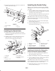
Installing the Double Pulley 2. Remove the two bolts, nuts, and rear cover plate from the back of the tractor (Fig. 3). Note: If you have a Rollover Protection System (ROPS) installed, refer to the next section for installing the double idler pulley. 3 1. Loosely, install the pulley mounting plate and top plate to the left hand rear axle with 4 bolts (3/8 x 3–1/2 inch) and 4 flange nuts (3/8 inch) (Fig. 5). 2.
5. Secure the double idler pulley with a flat washer (7/16 inch) and locknut (7/16 inch) (Fig. 5). 4 1 6 3 Installing the Drive Belt and Mower 1. Install the mower if it is not installed. Refer to the mower operators manual. 2. Route the drive belt under the linkage to the top pulley of the blade spindle and around the front idler V pulley (Fig. 6). 3. Route the drive belt onto the top pulley of the double pulley mounted on the tractor’s left side axle (Figures 7 and 12). 2 7 4.
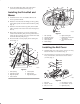
Installing the Collector 5. Pull the hitch lever up. This will raise the hopper and engage the collector pin into the hitch extension (Fig. 11). 1. Align the hinges on both halves of the collector. The halves must be positioned in the closed position (Fig. 9). 6. Pull the locking pin out to allow the collector to be raised into full upright position (Fig. 11). 2. Push the dumping arm through the hinges and secure with a cotter pin (3/16 x 1 in.) (Fig. 9). 4 2 7.
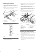
3. Install the boot onto the mower by lifting the mower discharge chute and sliding the boot bracket between the grass deflector and the mower deck (Fig. 14). 1 4. Release the grass deflector. This will lock the boot in place behind the bolt heads (Fig. 14). Note: The boot needs to fit snuggly to the mower. 5. If the bolts are not positioned correctly to lock to boot in place, loosen the bolts, slide them to the correct position so that the deflector locks the boot in place (Fig. 14). 6.
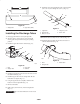
9. Install the upper and straight tube with 3 carriage bolts (1/4 x 3/4 in.) and 3 flange nuts (1/4 in.) (Fig. 17). B 1 2 4 A 5 1 3 m–6542 2 Figure 15 1. Straight tube m-5957 2. Upper tube (elbow) Figure 17 1. Upper tube 2. Straight tube 3. Bolt, 1/4 x 3/4 in. Installing the Discharge Tubes 4. Flange nut, 1/4 in. 5. 9/32 in. hole 1. Disengage the PTO and set the parking brake. 10. Install the tube assembly into the collector (Fig. 16). 2.
4. Raise the collector arm to the highest position and release the collector lever (Fig. 19). The locking pin will drop into a hole in the highest position. Operation Note: Determine the left and right side of the machine from the normal operating position. 5. Pull the collector arm down to raise the back of the collector (Fig. 19). Warning 6. Close the back of the collector and squeeze the collector lever (Fig. 19). 7. Lower the collector arm to the working position (Fig. 19).
Clearing Obstructions From the Collector 4. Open the collector; refer to Emptying the Quiet Collector, page 11. 5. With the collector open, pull out the holding pin and insert into the hole in the hinge (Fig. 20). 1. Empty the collector. 2. Disengage the mower PTO and set the parking brake. 1 3. Stop the engine, remove the key, and wait for all moving parts to stop before leaving the operating position. 2 4. Remove the tube assembly from the collector. 3 5.
Checking for Full Collector 8. Remove the collector belt (Fig. 12). 9. Remove the clevis pin and hairpin cotter from the left side of the collector (Fig. 11). 1. To determine when the collector is full, use the following two methods. 10. Unlatch the locking pin on the right–hand side of the collector (Fig. 11). A. Raise the gauge arm frequently (Fig. 22). If you feel resistance, it indicates the collector is full and needs to be emptied. 11. Remove the collector from the quick hitch (Fig. 11). B.
system, mow the grass at a high height-of-cut, then lower the mower to your normal cutting height and repeat the bagging process. Caution As the collector fills, extra weight is added to the back of the tractor. If you stop and start suddenly on hills, you may lose steering control or the tractor may tip. Bagging Wet Grass Always try to cut grass when it is dry because your lawn will have a neat appearance. If you must cut wet grass, use the conventional side discharge feature of the mower.
4. Tighten all nuts bolts and screws. 1. Wash the inside and outside of the collector, upper tube, middle tube, boot assembly and the underside of the mower. Use a mild automotive detergent to remove dirt. Inspecting the Mower Blades 2. Make sure you remove matted grass from all parts. 3. After washing all parts, let them dry thoroughly. 1. Inspect the mower blades regularly and whenever a blade strikes a foreign object. Lubricating the Idler Arm 2.
Problem Reduced bagging performance. Boot and tubes plug g too frequently. q y Debris blowout. Possible Causes Corrective Action 1. Low engine speed. 1. Always operate the collector at full throttle. 2. Plugged fan screen. 2. Remove debris, leaves or grass clippings from the fan screen. 3. Loose collector belt. 3. Check the collector belt tension. 4. Broken seal between hopper and rear door. 4. Ensure the rear door is latched. 5. A plugged boot. 5. Locate and remove plugged debris. 6.