
Installation Instructions

FORM NO. 3314-584 Rev. B
The TORO Company -
1991, Rev. 1992
TPS
INSTALLATION
INSTRUCTIONS
HIGH HEIGHT-OF-CUT KIT
PART NO. 83-5300
Reelmaster 5100 & 223D 5 Blade Cutting Units
1. While loosening locknuts, unthread the
capscrews from the top of rear H.O.C. brackets on cutĆ
ting unit.
2. Remove the carriage bolts and locknuts securing
rear H.O.C. brackets to cutting unit side plates.
3. Loosen set screws allowing rear roller to be reĆ
moved from H.O.C. brackets.
4. Slide new rear H.O.C. brackets onto the bearing
shafts on the rear roller. Do not tighten the set screws at
this time.
5. Loosely secure new rear H.O.C. brackets to cutting
unit sideplates with carriage bolts and locknuts preĆ
viously removed.
6. Rethread the top capscrews into rear H.O.C.
brackets.
7. Remove capscrews and locknuts securing front
roller support to cutting unit sideplates.
8. Remove set screws allowing front roller to be reĆ
moved from roller supports.
9. Install new roller supports to roller with set screws
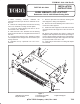
removed. Mount roller supports to roller as shown in
figure 1.
10. Secure roller supports and roller to cutting unit
sideplates with capscrews and locknuts previously reĆ
moved. Apply medium strength blue Loctite #242 to
the set screws securing the roller supports to the roller.
Torque set screws to 25-30 ft.- lbs.
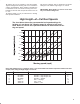
11. Level roller per instructions in Cutting Unit OperaĆ
tor's Manual.
1
2
3
4
5
7
9
9
6
11
11
10
10
8
Figure 1
1. Right Rear H.O.C. bracket
2. Sq. Hd. Set Screw
3. Left Rear H.O.C. bracket
4. Left Front Support
5. Right Front Support