
Operator's Manual


FORM NO. 3316-806 Rev. A
The TORO Company - 1994, Rev. 1997
INSTALLATION
INSTRUCTIONS
PART NO. 93-3149
TRACTION PEDAL KIT
Groundsmaster 300 Series
CAUTION
Before servicing or making adjustments to the
machine, stop engine and remove key from
switch.
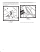
1. Remove nut securing front end of pump control
rod to traction pedal pivot bracket (Fig. 1).
Figure 1
1. Pump control rod
2. Traction pedal pivot bracket
3. Self tapping screws
1
3
2
2. Remove (2) self tapping screws securing top of
traction pedal pivot bracket to frame (Fig. 1). Remove
traction pedal assembly.
3. Using dimensions shown in figure 2, locate, mark
and drill 11/32" dia. hole in floor plate.
Figure 2
.69"
1.00"
11/32" dia.
4. Place new traction pedal assembly into position
and secure traction pedal pivot bracket to frame with
(2) new self tapping screws (Fig. 3).
Figure 3
1. Traction pedal assembly
1
5. Connect pump control rod to traction pedal pivot
bracket with nut previously removed (Fig. 3).