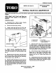
MODEL NO. 93-6175 FORM NO. 93-6179 SET-UP AND PARTS CATALOG L ‘MANUAL VALVE 8.S. ADAPTER KIT J Refer to the illustrated Parts List for the details of parts used in assembling the Manual Valve Spray System. NOTE: “Right’, "Left", "Front", and "Rear" are referenced while seated in the operator's position. CONTROL VALVE: 1. Disconnect the 3 Boom Hoses, Supply Hose, and Overflow Hose from Valve, 2. Remove old Valve from vehicle. 3. Locate, mark and drill two (2) 5/16" dia.
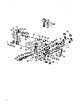
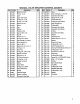
MANUAL VALVE SPRAYER CONTROL (93-0877) Ret Description Qty Hef | Part No. Description Qty 1 |Adjustment Knob 3 136 [93-0976 evasive 1 2 Pin Die, [08-0976 [Vito O-Ring Dia. 1.78 x 6.75 o 3 Aver 3 38 [93-0977 [Volumetric Valve Rod 1 4 Upper Valve Body 3 3¢ [93-0978 [Spring Pin Dia. -Ring Dia. 83-0071 Outlet Val's Ass'y 3 6 -Ring 1.78 x 7.66 3 41 193-0878 [O-Ring Dia. 2.62x 22.22 3 7 ashier Dia, 8.2 8| 142 [Pipe Fitting Dia.
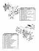
VALVE MOUNTING ASSEMBLY MANUAL SPRAY VALVE SET-UP Ref Part No. Description Gty T B G ROT RT [93-0877 93-0884 o3 o 93-8178 93-0886 03-0856 93-085 1 141327 3-6176 8177 1148 03-0881 -0888 [Control Valve Hose Cover, 1.18" D x 24" Hose Barb, 1° H.B. x MPT [Tee, NPT [Hose Barb, 90° MPT x HB Hose Barb, MPT x HE Hose Clamp Bypass Hose, x [Hose Bypass to Tank; 9* Hose Clamp Supply Hose, 1" x 24" Hose Cover, 1.59" Ref Part No.