
Installation Instructions


3
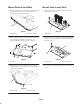
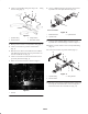
Mount Deck Guard Bars
1. Mount a long guard bar and (2) short guard bars to front
of center deck with 5/16–18 x 3/4” lg. capscrews.
Position guards as shown in figure 1.
1
2
Figure 1
1. Guard bar–long 2. Guard bar–short (2)
2. Mount appropriate (right or left) guard bar to front of
each center wing deck with 5/16–18 x 3/4” lg.
capscrews. Position guards as shown in figure 2.
1
Figure 2
1. Guard bar
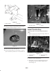
3. Mount a long and a short guard bar to front of each
wing deck with 5/16–18 x 3/4” lg. capscrews. Position
guards as shown in figure 3.
1
2
Figure 3
1. Guard bar–long 2. Guard bar –short
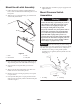
Mount Valve Lever Stop
1. Remove (2) screws securing front of center control
panel to chassis (Fig. 4).
1
Figure 4
1. Control panel
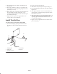
2. Mount valve lever stop pivots to control panel with (2)
1/4–20 x 1–1/4” lg. socket head capscrews. Position as
shown in figure 5.
1
2
Figure 5
1. Valve lever stop 2. Valve lever stop pivot
3. Pivot valve lever stop toward lift levers to disable lift
levers.