
Installation Instructions


4
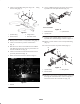
Mount Hood Latch Assembly
1. Follow directions on template (supplied with kit) to
locate, mark and drill hood latch mounting holes in rear
hood panel.
2. Affix decal, to rear hood panel (Fig. 6). Position decal
around newly drilled holes.
1
2
4
3
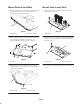
Figure 6
1. Decal
2. Latch handle
3. Latch
4. Latch plate
3. Insert hood latch handle through large drilled hole and
align mounting holes with small drilled holes (Fig. 6).
4. Secure handle to hood panel with (2) screws and
washers.
5. Thread a jam nut onto latch handle, insert latch onto
handle and secure with another jam nut.
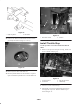
6. Remove (2) screws securing top (center) of rear panel
to top of chassis.
7. Loosely mount latch plate to top of panel and chassis
with (2) screws previously removed. Position latch plate
as shown in figure 6.
8. Adjust latch plate and latch for proper engagement and
tighten fasteners.
Mount Pressure Switch
Assemblies
Before disconnecting or performing any work on
the hydraulic system, all pressure in the system
must be relieved by stopping the engine and
lowering the cutting units to the ground.
Keep body and hands away from pin hole leaks or
nozzles that eject high pressure hydraulic fluid.
Use cardboard or paper to find hydraulic leaks.
Hydraulic fluid escaping under pressure can
penetrate skin and cause injury. Fluid accidentally
injected into the skin must be surgically removed
within a few hours by a doctor familiar with this
form of injury or gangrene may result.
Warning
Important Before disconnecting any hoses, fittings or
tube assemblies, note their orientation, location and routing.
This will ensure proper installation of new components.
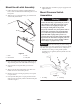
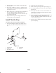
1. Disconnect 90 fitting securing left lift cylinder
hydraulic hose to right lift cylinder hydraulic hose Tee
fitting (Fig. 7).
1
2
Figure 7
1. 90 Fitting 2. Tee fitting