
Installation Instructions


5
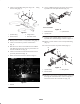
2. Connect new hydraulic fitting w/O–ring to 90 fitting
and Tee fitting (Fig. 8).
1
2
3
4
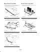
Figure 8
1. Hydraulic fitting
2. Pressure switch
3. Wiring harness
4. Ball switch location
3. Mount pressure switch to new hydraulic fitting (Fig. 8).
4. Connect new harness to pressure switch harness
(Fig. 8).
5. Disconnect wire harness from ball switch on R.H. lift
arm. Ball switch is located between pivot brackets on
left end of R.H. lift arm (Fig. 8).
6. Connect new harness to ball switch and wire harness
previously disconnected (Fig. 8).
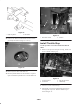
7. Route and secure the harness as shown in figure 9.
1
Figure 9
1. Harness
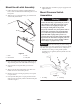
8. At rear of bulkhead bracket, disconnect (2) lower left
hydraulic hoses from hydraulic tubes (Fig. 10).
1
2
3
Front of machine
Figure 10
1. Bulkhead bracket
2. Hydraulic lines
3. Hydraulic tubes
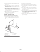
9. Connect a new hydraulic fitting w/O–ring to each
hydraulic tube. Position fittings as shown in figure 11.
10. Mount a pressure switch to each new hydraulic fitting
(Fig. 11).
11. Connect new harness to pressure switch (Fig. 11).
1
3
3
2
2
1
Figure 11
1. Hydraulic fitting
2. Pressure switch
3. Wiring harness
12. Disconnect wire harness’s from ball switch on right and
left wing lift arms. Ball switches are located by pivot
brackets on inside end of each lift arm (Fig. 12).