
Installation Instructions


6
1
2
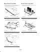
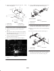
Figure 12
1. Right wing lift arm 2. Ball switch
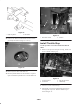
13. Connect new harness to ball switch and wire harness
previously disconnected (Fig. 12, 13 & 14).
Figure 13
14. Secure any loose wires with cable ties.
15. Check hydraulic fluid level and add fluid as required.
Operate machines hydraulics and re–check fluid level.
2
1
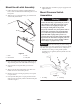
Figure 14
1. Ball switch location 2. Harness
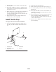
Install Throttle Stop
Use this procedure on traction unit models 30582 &
30583.
1. Remove cotter pin and clevis pin securing throttle rod
clevis to throttle arm (Fig. 15).
1
2
4
3
Figure 15
1. Throttle rod clevis
2. Throttle arm
3. High idle stop screw
4. Throttle stop
2. Loosen set screw on throttle stop.
3. Push throttle arm forward while sliding throttle stop
onto high idle stop screw. Position throttle stop as
shown in figure 15.