
Installation Instructions


7
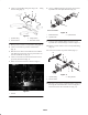
4. Re–install throttle rod to throttle arm with clevis pin
and cotter pin.
5. Start engine and allow to run for 5 to 10 minutes. The
engine must be at normal operating temperature before
proceeding to next step.
6. When cutting units are operating, high idle should be no
more than 2225 rpm. When cutting units are not
operating, high idle should be no more than 2310 rpm
or no less than 2260 rpm.
7. Tighten throttle stop setscrew. Apply adhesive into
setscrew hole to prevent tampering.
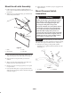
Install Throttle Stop
Use this procedure on traction unit model 30581.
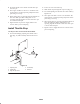
1. Loosen bolt clamping adjusting lever/throttle arm to
shaft (Fig. 15). Slide assembly off shaft. Do not lose
key.
1
3
4
5
2
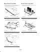
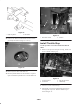
Figure 16
1. Adjusting lever
2. Throttle arm
3. High idle stop screw
4. Throttle stop
5. Setscrew
2. Loosen set screw on throttle stop.
3. Slide throttle stop onto high idle stop screw (Fig. 15).
4. Re–install adjusting lever/throttle arm to shaft with key.
Tighten bolt.
5. Start engine and allow to run for 5 to 10 minutes. The
engine must be at normal operating temperature before
proceeding to next step.
6. When cutting units are operating, high idle should be no
more than 2220 rpm. When cutting units are not
operating, high idle should be no more than 2260 rpm
or no less than 2100 rpm.
7. Tighten setscrew. Apply adhesive into setscrew hole to
prevent tampering.