
Installation Instructions

FORM NO. 3319-284
The TORO Company - 1996
TPS
INSTALLATION
INSTRUCTIONS
GROUNSMASTER
3000
PART NO. 95-3263
WIRE HARNESS KIT
CAUTION
Before servicing or making adjustments to the
machine, stop engine and remove key from
the switch.
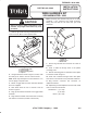
1. Remove (6) screws securing control panel to top of
control console. Move control panel to side.
Figure 1
1. Control console panel
2. Control console
3. Plastic mounting pad (3)
4. Capacitor
1
3
2
4
2. Using dimensions shown in figure 2, locate, mark
and drill (2) .50" holes in front of control console.
Note: Holes may already be in some machines. If so,
remove plugs to expose holes.
3. Mount a toggle switch in each hole with washers
and nuts supplied.
4. Affix switch decal to front of console cover as
shown in figure 2.
5. Plug (2) wire harness terminals onto toggle switch
terminals.
6. Plug harness terminal onto traction unit accessory
wire harness connector (located at fuse block).
Note: Accessory wire harness may not be on some
machines. If not, purchase and install Accessory
Wiring Kit, Toro Part No. 95-1691 from your local
distributor.
Figure 2
2
1. Console cover
2. Switch decal
4.00"
1.00"
2.00"
.50" Dia. (2)
1
7. Secure ring terminal wire of harness to screw on
capacitor.
8. Insert a cable tie through each of the plastic
mounting pads.
9. Affix the mounting pads to underside of floor plate
at locations shown in figure 1.
10. Insert end of harness through hole in floor plate
and secure to underside of floor plate with cable ties.
11. Plug harness connector into connector on
implement harness.
12. Depending on what implement is to be used, install
fuses in fuse block as follows:
Snowblower - (1) 5 amp
(1) 30 amp
Brush- (2) 5 amp