
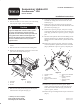
Installation Instructions

1
All Rights Reserved
Printed in the USA
2002 by The Toro Company
8111 Lyndale Avenue South
Bloomington, MN 55420-1196
Suspension Update Kit
Greensmaster
3200
Part No. 98-4611
Form No. 3319-887 Rev A
Installation Instructions
Disassembly
1. Park the machine on a level surface, lower the cutting
units, stop the engine, and set parking brake.
Operate all hydraulic controls to relieve system
pressure and avoid injury from pressurized
hydraulic oil. The controls must be operated with
the ignition switch in Run and the engine Off.
Return the ignition switch to Off when pressure
has been relieved. Remove the key from the
ignition switch
Caution
2. Remove the baskets from the cutting unit carrier
frames.
3. Disconnect the drive motors from the cutting units.
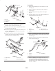
4. Remove the shoulder bolts securing the carrier frame
pull arms to the cutting units (Fig. 1).
1
3
2
4
5
Figure 1
1. Pull frame
2. Lift roller
3. Lift arm
4. Pull arm
5. Ball joint
5. Disconnect the ball joint housing from the ball joint
stud and remove the pull arms (Fig. 1).
6. Unhook the cutting unit lift rollers from the lift arms
and slide the cutting units out from under the carrier
frames (Fig. 1).
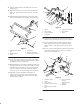
7. Remove the cotter pins and clevis pins securing the
hydraulic lift cylinders to the lift arms. Retain the cotter
pins and clevis pins (Fig. 2).
8. Remove the capscrew, pivot pin, and spacer securing
each front lift arm and carrier frame to the traction unit
frame (Fig. 2). Retain the capscrews, spacers, and pivot
pins.
9. Disconnect the hydraulic hoses from the fittings on the
front lift cylinders (Fig. 2). Note the orientation of the
fittings and remove them from the cylinders. Retain the
fittings.
10. Remove the capscrew, pivot pin, and spacer securing
each front hydraulic cylinder to the traction unit frame
(Fig. 2). Retain the capscrews, spacers, and pivot pins.
1
2
3 45
6
7
Figure 2
1. Hydraulic cylinder
2. Lift arm
3. Carrier frame
4. Pivot pin (carrier frame/lift
arm)
5. Spacer (carrier frame/lift
arm)
6. Pivot pin (hydraulic
cylinder)
7. Spacer (hydraulic
cylinder)
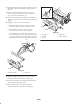
11. Remove the capscrew, flat washer, spacer, thrust
washer, and nut securing the rear lift arm and carrier
frame to the traction unit frame (Fig. 3). Retain the
capscrew, spacer, and nut.
12. Remove the grease fitting from the top of each lift arm
(Fig. 3).