Aqua-Clear Fiberglass Sand Filters Addendum to the Installation & Users Guide Automatic Backwash Filter Assembly See Installation & User’s Guide for Important Safety Instructions
System Contents........................................................................................................................ 3 Overview .................................................................................................................................... 5 Assembly of the Automatic Backwash valves ............................................................................. 5 Hydraulic Control Filter Assembly ..........................................................................
Automatic Backwash Filter Operating Manual Addendum System Contents Please check immediately to see that you have received all the parts for the system. For two filter systems, reference Table 1. For one filter expansion systems, reference Table 2. Systems may contain kits, the detailed contents of which appear in Table 3.
System Contents (cont.
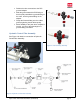
Overview Construct the manifold system shown below, using only schedule 40 PVC pipe and fittings. VERY IMPORTANT to always support the PVC manifolds or any long runs to prevent any added stress on the filter bulkheads and glue joints. In general, use as short a length of PVC pipe as practical, and do not add unnecessary fittings and elbows; this will prevent unnecessary pressure losses and improve efficiency. Figure 1 Assembly of the Automatic Backwash valves 1.
• • • • Position the valve connection to the PVC grooved adapter. Slide the gasket toward the PVC fitting so that it equally straddles the grooved fitting on the valve, and the grooved fitting on the adapter. Clamp the Grooved fitting over the rubber gasket, tightening the two bolts equally. Some flexibility of this joint when complete is normal; it is one of the advantages of a grooved fitting connection.
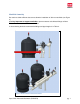
Manifold Assembly Be certain to allow sufficient clearance to allow the installation of all three manifolds (see Figure 4) It is Very Important to support manifolds to prevent stresses to bulkhead fittings on filters. Excessive stress can lead to failure of the filter. A chart showing the basic recommended fittings and pipe lengths is in Table 4. Figure 4 Manifold Clearance Recommendation Aqua-Clear Automatic Backwash (ENG/SPA) pg.
A detailed assembly diagram for these parts is in the appendix. Table 4 Parts toSource Locally Aqua-Clear Automatic Backwash (ENG/SPA) pg.
Assembly of the Air Vents See Figure 5. For the 18” and 24” models, the air vent is attached to the ¼” threaded nipple which comes attached to the manual air bleed assembly. The rest of the manual air bleed assembly is not needed. This ¼” threaded nipple is then installed onto the 6” closure on top of the filter. For the 30” and 36” models, the air vent adapter should first be installed on the 8” closure on top of the filter. The Air Vent can then be threaded onto this adapter.
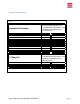
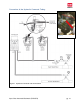
Connection of the Hydraulic Command Tubing Figure 6 Figure 7 Hydraulic Command Tube Connections Aqua-Clear Automatic Backwash (ENG/SPA) pg.
Hydraulic command tube serves two purposes in an automatic backwash system: 1. It communicates the pressure levels to the controller, which manages the backwash 2. It provides the pressure to open and close the backwash valves. Follow the circuit diagram in Figures 6,7 to connect the Hydraulic Command Tubing. The filter on the Hydraulic Command assembly assures that the water used to control the valves is clean of debris. This filter will become clogged over time, and should be cleaned.
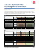
Programming the Automatic Backwash Controller General Information The controller comes with its own manual which provides good detail. The information below is abbreviated, and explains some terms found in the controller manual. The general function of the backwash controller is to sense the need for the filters to be backwashed, and to manage a backwash cycle in which each filter is individually flushed. As the filters become dirty and need to be flushed, the pressure loss through filters increases.
If you decide during the initial programming to change a variable which you have already passed, you can reach it by cycling all the way through the remaining functions to be programmed, and loop back to the function to be changed. Any time changes to the configuration settings are desired, this stage can be entered by pressing and holding the ENTER key. Program Settings Following is the sequence of controller functions that will appear after entering the programming cycle: 1.
5. Main Valve The standard controller is not equipped for this function; an expansion board can be added which enables the controller to command a master valve when a backwash cycle is triggered. Please speak with your Toro dealer if you wish to add this functionality. The standard setting should be “No” to indicate no main valve function. 6. Dwell Time The controller backwashes the filters one at a time. The Dwell time is the pause between the filters in a backwashing cycle.
12. Pressure Units Select PSI for US units, or Bar for metric units. 13. Calibration This will calibrate the PD sensor. While the controller sensor ports are disconnected from the hydraulic tubing, select the Calibration = Yes. The calibration occurs very quickly, and the sensor ports on the controller should be reconnected after passing through this program step. This will conclude the programming of the controller, and it is ready to use.
Wiring the Controller Solenoids Each of the solenoids must be connected to the board inside the controller, as shown in Figures 11, 12. DC models: The black wire from each solenoid should be attached to the common terminal (C) as shown in Figure 11. The red wires should be attached as shown to terminals Out A and Out B respectively. AC models: The solenoid wires will be the same color.
Powering the Controller DC Model The DC model requires four D Cell batteries, which should power the controller for a year. Install the batteries by removing the top of the controller, and installing four D size batteries as shown in Figure 13. The unit has two levels of low battery indication. When the battery voltage drops to the first level, the low battery sign will appear on the screen.
Figure 14 Finished Assembly Aqua-Clear Automatic Backwash (ENG/SPA) pg.
Appendix 1: Manifold Construction Detail Figure 15 Aqua-Clear Automatic Backwash (ENG/SPA) pg.
Aqua-Clear Filtros de Arena de Fibra de Vidrio Anexo a la Guía de Instalación y al Manual de Usuario Montaje del Filtro de Retrolavado Automático Véase la Guía de Instalación y el Manual de Usuario para obtener las Instrucciones de Seguridad Aqua-Clear Automatic Backwash (ENG/SPA) pg.
Contenido del Sistema ..............................................................................................................22 Información General .................................................................................................................24 Montaje de las Válvulas de Retrolavado Automáticas ...............................................................24 Montaje del Filtro de Control Hidráulico....................................................................................
Filtro de Retrolavado Automático Anexo al Manual de Usuario Contenido del Sistema Por favor verifique de inmediato que ha recibido todas las piezas del sistema. Para sistemas con dos filtros, consulte la Tabla 1. Para sistemas de expansión de un filtro, consulte la tabla 2. Los sistemas pueden contener paquetes, para verificar el contenido detallado consulte la Tabla 3. Tabla 1 Tabla 2 Aqua-Clear Automatic Backwash (ENG/SPA) pg.
Contenido del Sistema (continuación) Tabla 3 Contenido del Kit Hidráulico: Descripción Manómetro de Salida Tubo Hidráulico 8mm- Bobina 10' Disco de Filtro 3/4" Válcula de Escape Buje de Reducción 1/4" x 1/8, Latón Tee, Plástico [Compresión 8 mm x 1/8 NPT) Codo, Plástico [ Compresión 8 mm x 1/8" NPT] Tee, Plástico [Compresión 8 mm) Bridas Roscadas (2") Kit de Conectores 3" Tubería Ranurada (3") Niples Adaptador de Cubierta de Ventilación Aqua-Clear Automatic Backwash (ENG/SPA) El Kit Hidráulico de AquaC
Información General Construya el sistema de múltiples como se muestra en la ilustración de abajo, utilizando solamente la tubería PVC de cédula 40 y conectores. ES MUY IMPORTANTE asegurarse de reforzar la tubería de PVC del sistema de múltiples, o cualquier otro tubo de paso para evitar la acumulación de tensión en las bridas del filtro e inserciones.
• • • • Coloque la conexión de la válvula al adaptador ranurado de PVC. Deslice el empaque hacia el conector de PVC de modo que se extienda el conector ranurado en la válvula, y el conector ranurado al adaptador de PVC. Sujete el conector ranurado sobre el empaque de hule, apretando ambos tornillos. La flexibilidad con la que cuenta el ensamble una vez ya terminado es normal, pues es una de las ventajas de la conexión de tubería ranurada.
Montaje de los Múltiples Asegúrese de dejar suficiente espacio para realizar la instalación de los 3 (tres) múltiples (vea la ilustración 4). Es muy importante reforzar adecuadamente los múltiples para evitar el exceso de tensión en la bridas de los filtros, ya que esto puede resultar al fallo del filtro. Vea la Tabla 4, en la cual encontrará sugerencias de conectores así como longitudes de tubería. Ilustración 4 Montaje de los Múltiples Aqua-Clear Automatic Backwash (ENG/SPA) pg.
En el Apéndice 1, encontrará un diagrama detallado de las partes del montaje. Tabla 4 Partes a Conseguir Aqua-Clear Automatic Backwash (ENG/SPA) pg.
Montaje de Válvulas de Aire/Vacío Vea la ilustración 5. Para los modelos de 18” y 24”, la válvula de alivio de aire/vacío se encuentra adherida al niple roscado de ¼” el cual viene adjunto al Manual de Ensamble de la unidad de purga de aire. El resto del manual de ensamble no es necesario. Este niple roscado de ¼” será posteriormente instalado en el cierre de 6” en la parte superior del filtro.
Conexión de Tubería de Comando Hidráulico Conectar al Puerto #1 en Válvulas de Lavado Al ambiente CONTROLADOR Ilustración 6 Válvula de Lavado 2 BAJO Válvula de Lavado 1 ALTO MANÓMETRO VÁLVULA BOLA FILTRO ENTRADA DE MÚLTIPLE SALIDA DE MÚLTIPLE Ilustración 7 Conexión de Tubería de Comando Hidráulico Aqua-Clear Automatic Backwash (ENG/SPA) pg.
La Tubería de Comando Hidráulico tiene dos propósitos en un sistema de retrolavado automático: 1. Transmite los niveles de presión al controlador, el cual dirige el retrolavado. 2. Proporciona la presión para abrir y cerrar las válvulas de retrolavado. Siga el diagrama de circuito de las ilustraciones 6 y 7 para conectar la Tubería de Comando Hidráulico. El filtro del montaje del Comando Hidráulico se asegura de que el agua utilizada para controlar las válvulas esté limpia y libre de residuos.
Programación del Controlador de Retrolavado Automático Información General El controlador incluye el manual de usuario con instrucciones precisas para su uso. La información que se presenta a continuación explica brevemente algunos de los términos que se encuentran en el Manual de Usuario del controlador. La función general del controlador de retrolavado es detectar la necesidad de los filtros de ser lavados, y de administrar el ciclo en el cual cada filtro es lavado individualmente.
Si durante la programación inicial decide cambiar una variable anteriormente asignada, puede continuar pasando el resto de las funciones a programar y volver a programar la función deseada. Cualquier cambio de tiempo que se desee hacer en el ajuste de Configuración, puede realizarse pulsando y manteniendo presionada la tecla ENTER. Configuración del Programa A continuación se muestra la secuencia de las funciones del Controlador que aparecerán después de ingresar el ciclo de programación: 1.
5. Válvula Principal El controlador estándar no se encuentra equipado con esta función; una tarjeta de expansión puede ser añadida, lo que permite que el controlador ordene a la válvula principal cuando el ciclo de retrolavado inicie. Por favor comuníquese con su distribuidor autorizado de Toro, en caso de que desee agregar esta función. Indique ‘No’ en el ajuste estándar para la válvula principal. 6. Tiempo de Espera El controlador realiza su función de retrolavado con los filtros de uno en uno.
12. Unidades de Presión Seleccione las unidades de presión, ‘PSI’ en el estándar norteamericano; o ‘Bar’ en el sistema métrico. 13. Calibración Esto calibrará el sensor de DP. Mientras que los puertos del sensor del controlador permanecen sin conexión con la tubería hidráulica, seleccione ‘SI’ en Calibración. La calibración se produce rápidamente, y los puertos de los sensores del controlador deben volver a conectarse después de pasar a través de este paso del programa.
Diagrama de Cableado del Controlador Bobinas Cada una de las bobinas debe estar conectada a la placa dentro del controlador, como se muestra en las ilustraciones 11, 12. Modelos DC: El cable negro de cada bobina debe unirse a la terminal común (C) como los muestra la ilustración 11. Los cables color rojo deben unirse como lo muestran las terminales de salida A y B, respectivamente. Modelos AC: Los cables de la bobina serán del mismo color.
Encendido del Controlador Modelo DC El modelo DC requiere cuatro baterías tipo D, las cuales permitirán el funcionamiento del controlador por un año. Coloque las baterías, removiendo la parte superior del controlador y colocándolas como lo muestras la ilustración 13. La unidad cuenta con dos niveles que indican bacteria baja. Cuando el voltaje de la batería desciende hasta el primer nivel, la señal de batería baja aparecerá en la pantalla.
Ilustración 14 Montaje Final Aqua-Clear Automatic Backwash (ENG/SPA) pg.
Apéndice 1: Construcción Detallada de Múltiple Aqua-Clear Automatic Backwash (ENG/SPA) pg.
The Toro Company Micro-Irrigation Business 1588 N. Marshall Avenue El Cajon, CA 92020-1523, USA Tel: +1 (800) 333-8125 or +1 (619) 5622950 Fax: +1 (800 892-1822 or +1 (619) 2589973 Toro.com ALT 227 Aqua-Clear Automatic Backwash (ENG/SPA) pg.