Form No. 3418-252 Rev A 4-in-1 Electric/Hydraulic Bucket TX 1000 Compact Tool Carrier Model No. BU-003895 Model No. BU-003915 Model No. BU-004001 Register at www.Toro.com.
g000502 Figure 2 Safety-alert symbol Introduction Read this information carefully to learn how to operate and maintain your product properly and to avoid injury and product damage. You are responsible for operating the product properly and safely. This manual uses 2 words to highlight information. Important calls attention to special mechanical information and Note emphasizes general information worthy of special attention. You may contact Toro directly at www.Toro.
Slope Safety Safety • Operate the machine up and down slopes with the heavy end of the machine uphill. Weight distribution changes with attachments. An empty bucket makes the rear of the machine the heavy end, and a full bucket makes the front of the machine the heavy end. Most other attachments make the front of machine the heavy end. DANGER There may be buried utility lines in the work area. Digging into them may cause a shock or an explosion.
Attachment Safety Before Digging • Wear gloves, eye protection, long pants, To prevent damage and disruption to underground pipe and cable networks in your proposed excavation site, contact the Dial Before You Dig service. You can dial 1100 to access plans for underground networks anywhere in Australia. You may also log onto www.dialbeforeyoudig.com.au for additional information. substantial slip-resistant footwear, and hearing protection during operation or while adjusting or repairing the machine.
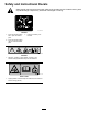
Safety and Instructional Decals Safety decals and instructions are easily visible to the operator and are located near any area of potential danger. Replace any decal that is damaged or missing. decal136-5844 136-5844 1. Press the joystick switch left to open the bucket jaws. 3. Lock the accessory into Forward. 2. Press the joystick switch right to close the bucket jaws. decal100-4648 100-4648 1. Warning; crushing of arm hazard; crushing of leg hazard—keep bystanders away from the machine.
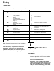
Setup Loose Parts Use the chart below to verify that all parts have been shipped. Procedure 1 2 3 4 5 6 7 8 9 Description Use Qty. No parts required – Connector mount bracket 7-pin connector Bolt (5/32 inches) Spacer Nut (5/32 inches) Relay and loader arm harness Plug nut Grommet Wire harness retainer Screw Self-tapping screw Relay Fuse (5 A) 1 1 2 2 2 1 1 No parts required – Remove the existing lever. No parts required – Install the 4-in-1 bucket lever.
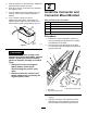
2. Park the machine on a level surface, engage the parking brake and lower the arms. 3. Shut off the engine, remove the key and allow the engine to cool. 4. Turn the battery-disconnect switch to the off position; refer to your machine Operator’s Manual. 5. If your machine does not have a battery-disconnect switch, disconnect the negative (black) cable from the battery, then disconnect the positive (red) cable (Figure 4).
3 Connecting the Loader Arm Branch Parts needed for this procedure: 1 Relay and loader arm harness 1 Plug nut Grommet 1 Wire harness retainer 2 Screw g242236 Figure 6 1. Bulkhead coupler locknut Procedure 2. Connector mount bracket 1. 5. Remove the plug and connect the hose fitting removed in step 2. Torque the fitting to 60 to 74 ft-lb (81 to 100 N·m). 6. Remove the grommet and plug nut from the rear of the 7-pin connector, as well as the parts bag inside the connector. 7.
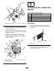
g242240 Figure 9 1. Screw 3. Spacer tube 2. Hose hold-down plate 4. Loader arm 3. g006230 Figure 10 Relay and loader arm harness connections Find the loader end branch of the relay and loader arm harness (Figure 10). 9 1. Relay branch 3. Power lead branch 2. Loader arm/attachment lever connector 4.
4. Route the loader end branch into the rear of the machine along the lower front end of the loader arm valve assembly (Figure 11) and out through the right hose access (Figure 12). 5. Route the loader end branch up into the outer protective sleeve, then route it along the bottom of the inner hydraulic hose so that the wires reach the 7-pin connector. 6. Install the plug nut (large) and then the grommet (small, narrow end facing the 7-pin connector) over the wires. g242387 g242237 Figure 11 1.
8. Tighten the terminal screws and pull on the wires to ensure that they are securely connected. 9. Install the wire harness retainer and 2 screws (Figure 14). 10. Install the connector top half and screw on the plug nut securely, at the same time seating the grommet (Figure 15).
4. Connecting the Power Lead Branch Install the 2 relays to the bucket relay connectors and continue to Connecting the Power Lead Branch (page 12). 1. Assembling the Relay Connectors to the Machine Important: Route the wire harness away from any hot or moving parts, secure with cable ties as needed. For Model 22327 with serial numbers after 316000467 and Model 22328 with serial numbers after 316999999 1.
6. Install the 5 A fuse into the inline fuse block on the power lead branch. 5 Removing the Existing Lever No Parts Required Procedure 1. g242427 Figure 22 Remove the retaining ring from the loader arm/attachment tilt lever shaft and move the washer up (Figure 20). 1. Drill a 5 mm diameter hole for the lever connector wire 2. Cut a 30 mm slot from the centre of the drilled hole 3. 10 mm from the edge of the existing hole to the centre of the new hole g242495 Figure 20 2.
8. 6 Attach the handle instructional decal onto the bottom left corner of the control panel decal as shown in Figure 24. Note: Clean and prepare the control panel decal before installing the handle decal. Installing the 4-in-1 Bucket Lever No Parts Required Procedure 1. Ensure that the rocker switches at the top of the 4-in-1 bucket lever are at right angles to the shaft opening as shown in Figure 23 and tighten the handle locknut. 2.
7 Installing the Valve Manifold Solenoid Harness No Parts Required Procedure 1. Remove the 4 bolts and washers securing the manifold cover from the 4-in-1 bucket (Figure 25). g242609 Figure 26 1. Valve manifold 3. Valve manifold solenoid harness 2. Left and right solenoid connectors 4. g242611 Figure 25 1. Manifold cover 2. Bolt and washer (4) 2. Feed the solenoid connector end of the valve manifold solenoid harness down the outer protective sleeve of the 4-in-1 bucket hoses. 3.
5. Lift up the spring-loaded cover on the 7-pin connector and insert the valve manifold solenoid harness connector (Figure 26). 4. Turn the low flow switch on to activate the auxiliary hydraulics low flow system. 5. Set the throttle to fast and lock the auxiliary hydraulics lever in the forward flow position; refer to your machine Operator’s Manual. Important: Operate the bucket jaws only with the auxiliary hydraulics lever in the forward flow position. 6.
Product Overview 9 Completing the Installation No Parts Required Procedure 1. Tilt the 4-in-1 bucket back and lower the loader arm. 2. Shut off the engine and remove the key. 3. Check all hydraulic connections for leaks and correct as necessary. 4. Check the hydraulic fluid level and correct as necessary; refer to your machine Operator’s Manual. g242329 Figure 28 5. Install the heat shield as shown in Figure 18. 6. Close and secure the engine hood. 1. 4-in-1 bucket 7.
Loader Arm/Attachment Tilt Lever Specifications Use the loader arm/attachment tilt lever to operate the 4-in-1 bucket (Figure 30). Note: Specifications and design are subject to Important: For the bucket jaws to operate, you 4-in-1 Extra High Volume Bucket change without notice. must have the auxiliary hydraulics lever in the forward detent position. Model BU003915 Width 1346 mm (53 inches) Length 804 mm (31.7 inches) Height 558 mm (22 inches) Weight 212 kg (467.
Maximum Material Density at Capacity The density of the materials moved by the bucket varies and, therefore, so does the amount of material that the bucket can carry before reaching the maximum load rating. The tables in Specifications (page 18) list the density of material that can be carried, both heaped and struck (i.e., leveled off), in the bucket. The table below lists common materials and their densities.
Operation CAUTION Hydraulic couplers, hydraulic lines/valves, and hydraulic fluid may be hot. If you contact hot components, you may be burned. The 4-in-1 bucket can be used in 4 different operating modes: • • • • Bucket • Wear gloves when operating the hydraulic couplers. Blade Leveller • Allow the machine to cool before touching hydraulic components. Grapple bucket • Do not touch hydraulic fluid spills.
Bucket Operation You can draw the jaws together to use this attachment as a standard bucket. You can also open the 4-in-1 bucket jaws to dump the contents into a higher area than a standard bucket can reach. When loading material, always have the bucket level to the ground and move forward into the material to be lifted. When the bucket is full, tilt it rearward to decrease the lifting resistance when you lift the load. When transporting a load, keep the bucket as close to the ground as possible.
Maintenance Recommended Maintenance Schedule(s) Maintenance Service Interval Before each use or daily Maintenance Procedure • • • • • • • Lubricate the bucket Ensure that all fasteners are securely tightened. Inspect the hydraulic system for leaks and loose fittings. Clean the areas around the bucket cylinder and mount plate pivot. Check for wear of pins, linkages, and cutting edges. Grease the bucket pivot points.
Storage 1. Before long-term storage, wash the attachment with mild detergent and water to remove dirt and grime. 2. Check and tighten all bolts, nuts and screws. Repair or replace any part that is damaged or worn. 3. Ensure that all the hydraulic hose couplers are connected together to prevent contamination entering the hydraulic system. 4. Paint all scratched or bare metal surfaces. Note: Paint is available from your Authorized Service Dealer. g242385 Figure 35 Some parts not shown for clarity 1.
Troubleshooting Problem Bucket does not open or close. Possible Cause Corrective Action 1. Electrical circuit issue. 1. Inspect the wire harness and electrical connections. Refer to the wiring diagram. 2. The fuse(s) are blown. 3. There are loose power or earth connection(s). 4. There are disconnected wire(s) at system terminal(s). 5. There are open or short circuit(s) in the wire(s). 6. The wire harness relay(s) are not functioning correctly. 7.
Schematics g239505 (Rev.
Notes:
Notes:
The Toro Warranty 4 in 1 bucket Conditions The Toro® Company and its affiliate, Toro Warranty Company, pursuant to an agreement between them, jointly warrant your Toro Product (“Product”) to be free from defects in materials or workmanship. The warranty applies from the date of the Product is delivered to the original retail purchaser: Where a warrantable condition exists, we will repair the Product at no cost to you including diagnosis, labour and parts.