
Operator's Manual

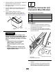


4.Routetheloaderendbranchintotherearofthe
machinealongthelowerfrontendoftheloader
armvalveassembly(Figure11)andoutthrough
therighthoseaccess(Figure12).
g242387
Figure11
1.Loaderendbranch2.Righthoseaccess
g242409
Figure12
1.Righthoseaccess
3.Outerprotectivesleeve
2.Loaderendbranch
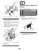
5.Routetheloaderendbranchupintotheouter
protectivesleeve,thenrouteitalongthebottom
oftheinnerhydraulichosesothatthewires
reachthe7-pinconnector.
6.Installtheplugnut(large)andthenthegrommet
(small,narrowendfacingthe7-pinconnector)
overthewires.
g242237
Figure13
1.Plugnut
2.Grommet
7.Removethetophalfofthe7-pinconnectorand
installthe4loaderendwiresintothecorrect
connectorterminalsinsideasshowninFigure
14.
g242270
Figure14
1.Wireharnessretainer4.Yellow-Terminal2
2.White-Terminal65.Black-Terminal7
3.Black-Terminal5
10