
Operator's Manual


8.Tightentheterminalscrewsandpullonthewires
toensurethattheyaresecurelyconnected.
9.Installthewireharnessretainerand2screws
(Figure14).
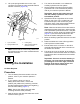
10.Installtheconnectortophalfandscrewonthe
plugnutsecurely,atthesametimeseatingthe
grommet(Figure15).
g242272
Figure15
1.Threadtheplugnutonto
the7-pinconnector
2.Connectortophalf
11.Installthehosehold-downplatesandspacer
tubesremovedinstep2.
Important:Ensurethatthewireharnessis
nottootautatthe7-pinconnector;givethe
harnesssufcientslackbeforetightening
thehold-downplates.
12.Replacethepreviouslyremovedscrewswith2
longerscrews(5/16–18TPIx1.75inches).
Note:Thesescrewsarenotsuppliedwiththe
attachment.
4
ConnectingtheRelayand
PowerLeadConnectors
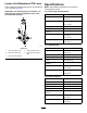
Partsneededforthisprocedure:
2
Self-tappingscrew
2Relay
1
Fuse(5A)
AssemblingtheRelayConnectors
totheMachine
ForModel22327withserialnumbersprior
to316000467andModel22328withserial
numberspriorto316999999
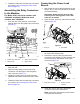
1.Fromtherearofthemachine,positionthe
relayconnectorsonthelowerrearfaceofthe
auxiliaryvalvebracketandmarkthelocationof
themountingholesonthebracket.
g242413
Figure16
1.Auxiliaryvalvebracket3.Relayconnectors
2.Drillahole(4mm)here.4.Self-tappingscrews
2.Drillholes(2)usinga4mmdrillbitatthemarks
madeinstep1.
3.Usingthe2self-tappingscrews,installtherelay
connectorstotheauxiliaryvalvebracket(Figure
16).
11