
Operator's Manual


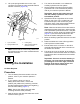


5.Liftupthespring-loadedcoveronthe7-pin
connectorandinsertthevalvemanifoldsolenoid
harnessconnector(Figure26).
g242610
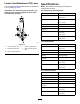
Figure27
1.7-pinconnector3.Lockingtang
2.Spring-loadedcover4.Valvemanifoldsolenoid
harnessconnector
Note:Ensurethatthecoverisfullyclosedover
thelockingtangsonthevalvemanifoldsolenoid
harnessconnector.
8
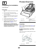
TestingtheInstallation
NoPartsRequired
Procedure
1.Turnthebattery-disconnectswitchtotheON
position;refertoyourmachineOperator’s
Manual.
2.Ifyourmachinedoesnothavea
battery-disconnectswitch,connectthe
positive(red)cabletothepositive(+)terminal
andthenegative(black)cabletothenegative(-)
terminalofthebattery(Figure4).
Note:Securethecablesusingthecable
mountinghardwareusedpreviously.
3.Starttheengineandraisetheloaderarmsothe
bucketisofftheground.
4.Turnthelowowswitchontoactivatethe
auxiliaryhydraulicslowowsystem.
5.Setthethrottletofastandlocktheauxiliary
hydraulicsleverintheforwardowposition;
refertoyourmachineOperator’sManual.
Important:Operatethebucketjawsonly
withtheauxiliaryhydraulicsleverinthe
forwardowposition.
6.Operatetheleftandrightsidesoftherocker
switchontopofthe4-in-1bucketlever;the
bucketshouldopenandcloseandagreen
LEDwithineachofthevalvemanifoldsolenoid
harnessconnectorsshouldilluminate.
Note:Whentheleftsideoftherockerswitchis
depressedthejawsshouldopen,whentheright
sideispressedthejawsshouldclose.Ifthejaws
open/closeinreverse,loosenthehandlelocknut
(Figure23)andscrewthehandledown180°.
Securethehandleandtightenthelocknut.
7.Movetheauxiliaryhydraulicslevertotheneutral
position.
8.Raisetheloaderarmtothehalfwayposition
andfullytiltthebucketforward.
9.Ensurethatthereisnotensiononthevalve
manifoldsolenoidharnessattheconnectionto
theloaderarmharness.
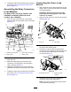
10.Fullydumpandcurlthebucket;atthemidpoint
ofthismotionensurethatthehosesdonotbend
excessivelyattheirconnectionstothemanifold
assembly.
Important:Ifthereisexcessivebendingin
thehoses,youmustloosenandadjustthe
portttingstocorrecttheangle;excessive
bendingofthehosescausesstressand
damagetothehosesandttings.
16