Landscape Dripline Design
Landscape Dripline Design_____________________________________________________________ ■ Table of Contents Table of Contents Introduction . . . . . . . . . . . . . . . . . . . . . . . . . . . . . . . . . . . . . . . . . . . . . . . . . . . . . . . . . . . . .1 i Terminology . . . . . . . . . . . . . . . . . . . . . . . . . . . . . . . . . . . . . . . . . . . . . . . . . . . . . . . . . . . .2-3 General Design Parameters . . . . . . . . . . . . . . . . . . . . . . . . . . . . . . . . . . . . . . . . . .
_____________________________________________________________Landscape Dripline Design ■ Introduction Toro provides more than just irrigation products — we provide turf solutions. For more than forty-five years, we’ve supplied a full line of quality irrigation equipment to fit any turf need. Customers have grown to trust Toro because we translate new technology into productive irrigation products for every turf requirement.
Terminology Landscape Dripline Design _____________________________________________________________ ■ Terminology 2 Application Rate — the rate at which a subsurface grid applies water to a specific zone, over a given period of time, measured in inches per hour. Backflow Prevention Device — the device, required by law, on an irrigation system that prevents water from re-entering the potable water lines once it flows into the irrigation pipes.
_____________________________________________________________Landscape Dripline Design ■ Terminology NOTES: Manifold — a group of control valves located together in the same area. O.D. — the abbreviation for “outside diameter.” PSI — the abbreviation for “pounds per square inch;” unit of measure for water pressure. PVC Pipe — Poly Vinyl Chloride pipe; the most common pipe used in irrigation systems. P.O.C. — abbreviation for “point of connection.
Design Parameters Landscape Dripline Design _____________________________________________________________ ■ General Design Parameters 4 Design Parameters Toro dripline is designed for use in applications using the grid concept, with supply and flush manifolds at each end to create a closed-loop system. The result of the grid design is a completely subsurface-wetted area that is ideal for plant growth and root development.
_____________________________________________________________Landscape Dripline Design ■ General Design Parameters Potable water, the most common type of water used in landscape applications, has relatively little debris and chemical contamination. Therefore, it only needs to be filtered with a screen or disk filter. With other water sources, it is advisable to obtain a water analysis prior to designing and installing the system.
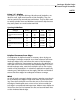
Landscape Dripline Design _____________________________________________________________ ■ General Design Parameters NOTES: Narrow, linear tree and shrub plantings require narrow, linear subsurface grids consisting of two to four laterals. More intense plantings that provide a complete foliage canopy at maturity require a grid design that applies uniform moisture levels within the foliage canopy (turf, groundcover, and dense shrub and tree plantings). Use the Spacing Guidelines Table (Table 1.
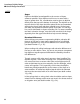
_____________________________________________________________Landscape Dripline Design ■ General Design Parameters NOTES: Using 1/4” dripline Toro’s two 1/4” dripline offerings, Microline and Soakerline, are ideal for small, tight areas because of their flexibility. They can also be used to loop around trees and bushes. They’re often used to retrofit sprinkler risers and bubblers to subsurface drip because they easily attach to a multi-outlet manifold.
Landscape Dripline Design _____________________________________________________________ ■ General Design Parameters NOTES: Slopes Driplines should be located parallel to the contour of slopes whenever possible. Since dripline runoff occurs on areas with a slope of greater than 3%, consideration must be given to dripline density from the top to the bottom of the slope. The dripline on the top two-thirds of the slope should be placed at the recommended spacings for the soil type and plant material in use.
_____________________________________________________________Landscape Dripline Design ■ Typical Design Procedures Design a typical dripline installation for zone #1 where the width is 5’ and the length is 50’. Flat, Sandy Soil Area Is In Constant Shade 50’ 1 P.O.
Landscape Dripline Design _____________________________________________________________ ■ Typical Design Procedures NOTES: Design Worksheet Use this worksheet to determine the type and quantity of product required for the system. DW1 Allowable Water Supply ____________ GPM DW2 Dynamic Pressure ____________ PSI Zones* 1 2 3 4 5 6 DW3 Soil Texture DW4 Plant Type DW5 Slope % DW6 Dripline Product DW7 Emitter Spacing DW8 Max. Dripline Lateral Spacing DW9 Nominal Flow Rate DW10 Actual Flow Rate DW11 Max.
_____________________________________________________________Landscape Dripline Design ■ Typical Design Procedures Step 3: Note the site and environmental parameters. ■ Soil texture (clay, loam or sand): ____________ (DW3) ■ Plant material(s) (trees, shrubs, ground cover or turf): ____________ (DW4) ■ Direction and degree of slope: ______________% (DW5) NOTES: Step 4: Lay out the laterals. ■ Use Table 2.2 below to determine the type of dripline product necessary to fit the irrigation needs of the site (i.
Landscape Dripline Design _____________________________________________________________ ■ Typical Design Procedures NOTES: Step 4: Lay out the laterals: (cont.) ■ Using the Spacing Guidelines Table, determine the nominal emitter flow rate. Nominal emitter flow rate: __________ GPH (DW9)* * Actual flow is a function of pressure. Use the Flow vs. Pressure Table (Table 2.4) to determine actual flow per emitter: __________ GPH (DW10) EMITTER FLOW (IN GPH) VS. PRESSURE Tube Dia.
_____________________________________________________________Landscape Dripline Design ■ Typical Design Procedures NOTES: Step 4: Lay out the laterals: (cont.) ■ Calculate the exact lateral spacing based on the dimensions of the area to be irrigated with subsurface drip. Perimeter Perimeter Spacing 2”-4” Widest Width Dripline Lateral Lateral Spacing Lateral Area Perimeter Spacing 2”-4” Perimeter TABLE 2.6 A. Measure, in inches, the subsurface drip area at its widest width. Width: ________ inches B.
Landscape Dripline Design _____________________________________________________________ ■ Typical Design Procedures NOTES: ■ Step 4: Lay out the laterals: (cont.) D. Divide the lateral area (as determined in Step C above) by the recommended lateral spacing (DW8) to obtain the total number of spaces between laterals. Round off to the nearest whole number to determine the exact number of spaces necessary to cover the drip area. Lateral area = _______ spaces between driplines Dripline lateral spacing E.
_____________________________________________________________Landscape Dripline Design ■ Typical Design Procedures NOTES: ■ Step 7: Calculate the total estimated gallons per minute (GPM) per zone by using one of the two following methods. Be sure to use the total estimated dripline per zone (see Step 6-A above). Zone flow: _________ GPM (DW13) - Determine the total number of drip emitters in each zone, then calculate the flow per zone based on the total flow rate of all drippers.
Landscape Dripline Design _____________________________________________________________ ■ Typical Design Procedures NOTES: ■ Step 8: Locate and size both the supply and flush manifolds in each zone. Both manifolds should be sized to accommodate the entire flow of the zone in GPM. (For details, refer to the Toro Technical Data Book, Form No. 490-1737). ■ Step 9: Determine the number and location of the flush caps for each zone at a minimum of 10 PSI.
_____________________________________________________________Landscape Dripline Design ■ Typical Design Procedures NOTES: ■ Step 11: Size pressure regulators based on the total zone flow using the table below.
Irrigation Scheduling Landscape Dripline Design _____________________________________________________________ ■ Irrigation Scheduling Irrigation scheduling with dripline uses the same methods of calculation as with sprinklers. The dripline grid system is designed to wet the irrigated area completely by methods similar to those used with sprinklers, supplying water in inches per hour.
_____________________________________________________________Landscape Dripline Design ■ Irrigation Scheduling NOTES: Zone Run Time Scheduling Worksheet To determine zone run times, obtain the following information: ■ monthly evapotranspiration value for the location ■ irrigation application rate (For regional ET data, refer to the Toro Rainfall and Evapotranspiration Data Book, Form No. 490-1358.) The following formulae can be used to determine run times.
Landscape Dripline Design _____________________________________________________________ ■ Installation Procedures Special Considerations for Subsurface Installations Installation Procedures 1. The typical recommended pipe depth for dripline is 4” below finished grade. 2. For turf areas where aerification is part of normal maintenance operations, tubing must be buried below the reach of aerification equipment. 3.
_____________________________________________________________Landscape Dripline Design ■ Installation Procedures NOTES: Planting Guidelines 1. Pre-irrigate to ensure that the soil is hydrated to field capacity before planting begins. This is especially important when planting sod or hydroseeding. 2.
Landscape Dripline Design _____________________________________________________________ ■ Installation Procedures NOTES: Installation Steps ■ Assemble and install filter, remote control valve and pressureregulating valve assembly(ies) according to detail numbers 1 and 2, p. 23. ■ Assemble and install supply header(s) according to detail numbers 3, 5, 4 and 6, p. 24-25. Tape or plug all open connections to prevent debris contamination.
_____________________________________________________________Landscape Dripline Design ■ Recommended Installation Instructions DZK-EZF-075-LF 9. TORO EZF-26-04 INLINE VALVE.(*) 2. CONTROL WIRES WITH 36” SERVICE COIL AND WATERPROOF WIRE CONNECTIONS, DBY OR EQUAL. 10. TORO 150 MESH Y-FILTER.(*) 3. RECTANGULAR PLASTIC VALVE BOX. HEAT BRAND STATION NUMBER ON LID IN 2” HIGH CHARACTERS. 4. PVC MAINLINE PER SPECIFICATIONS (LENGTH AS REQUIRED). 11. TORO 25 PSI LOW-FLOW PRESSURE REGULATOR.(*) 12.
Landscape Dripline Design _____________________________________________________________ ■ Recommended Installation Instructions Detail No.3 Center-Feed Sub-Manifold 1. FINISH GRADE. 6. PVC TEE (SxSxS). 2. DEPTH OF TUBING PER SPECIFICATIONS. 7. DRIPLINE LATERAL. 3. DEPTH OF PVC SUPPLY MANIFOLD PER SPECIFICATIONS. 8. PVC SUB-MANIFOLD. 4. PVC CROSS (SxSxSxS). 5. TORO COMPRESSION ADAPTER (T-CA-710). 9. PVC TEE (SxSxS). 10. PVC SUPPLY MANIFOLD FROM DRIP ZONE KIT. Detail No.
_____________________________________________________________Landscape Dripline Design ■ Recommended Installation Instructions Detail No.5 1. FINISH GRADE. 6. PVC TEE (SxSxS). 2. DEPTH OF TUBING PER SPECIFICATIONS. 7. DRIPLINE LATERAL. 3. DEPTH OF PVC SUPPLY MANIFOLD PER SPECIFICATIONS. 8. PVC SUB-MANIFOLD. 4. PVC TEE (SxSxT). 5. TORO LOC-EZE X 1/2” MPT ADAPTER (T-FAM16). End-Feed Supply Sub-Manifold 9. PVC TEE (SxSxS). 10. PVC SUPPLY MANIFOLD FROM DRIP ZONE KIT. Detail No.
Landscape Dripline Design _____________________________________________________________ ■ Recommended Installation Instructions Detail No.7 Center-Feed Layout 1. TORO AUTOMATIC FLUSH VALVE (T-FCH-H-FIPT) PLUMBED TO FLUSH MANIFOLD AT LOW POINT. 2. PVC FLUSH MANIFOLD. 3. TORO MANIFOLD-TO-ELBOW CONNECTION (TYP). DIRECTION OF FLOW HIGH POINT ON SLOPE 1 2 3 Detail No.8 4 End-Feed Layout 1. DRIPLINE LATERAL. 2. AREA PERIMETER. 3. DL2000 OPERATION INDICATOR (T-DL-MP9), OPTIONAL.* 4.
_____________________________________________________________Landscape Dripline Design ■ Recommended Installation Instructions Detail No.9 1. 1” ABOVE FINISH GRADE. 2. NATIVE SOIL PER SPECIFICATIONS. 3. FINISH GRADE. 4. TORO AIR/VACUUM RELIEF VALVE (T-YD-500-34). 5. 1/2” PVC COUPLING (TxT). 6. 6” ROUND PLASTIC VALVE BOX. HEAT BRAND “AR” ON LID IN 1” HIGH CHARACTERS. 8. BRICK SUPPORTS (2 COMMON BRICKS REQUIRED). 9. PEA GRAVEL SUMP (6” DEEP). 1/2” Air/Vacuum Relief Valve (Plumbed to PVC Tee) 10.
Landscape Dripline Design_____________________________________________________________ ■ Recommended Installation Instructions Detail No.11 1/2” Air/Vacuum Relief Valve (Plumbed to tubing) 1. 1” ABOVE FINISH GRADE. 2. FINISH GRADE. 3. 6” ROUND PLASTIC VALVE BOX. HEAT BRAND “AR” ON LID IN 1” HIGH CHARACTERS. 4. TORO AIR/VACUUM RELIEF VALVE (T-YD-500-34). 6. TORO DRIPLINE OR BLUE STRIPE POLY TUBING (T-EHD1645-XXX) AIR RELIEF LATERAL. 7. PEA GRAVEL SUMP (6” DEEP). 8.
_____________________________________________________________Landscape Dripline Design ■ Recommended Installation Instructions Detail No.13 1. 1” ABOVE FINISH GRADE. 2. FINISH GRADE. 3. TORO FLUSH VALVE (T-FCH-H-FHT). 4. TORO LOC-EZE X 3/4” MHT ADAPTER (T-FJA16). 5. TORO BLUE STRIPE POLY TUBING (T-EHD1645-XXX). 6. TORO DRIPLINE OR BLUE STRIPE POLY TUBING (T-EHD1645-XXX). 7. 6” ROUND PLASTIC VALVE BOX. HEAT BRAND “AR” ON LID IN 1” HIGH CHARACTERS. Automatic Flush Valve 8. TORO LOC-EZE ELBOW (T-FEE16). 9.
Landscape Dripline Design _____________________________________________________________ ■ Recommended Installation Instructions 1. PVC LATERAL LINE FROM DRIP ZONE KIT. 2. PVC SUPPLY MANIFOLD. 3. MANIFOLD-TO-ELBOW CONNECTION (TYP). 4. DRIPLINE LATERAL. 5. AIR/VACUUM RELIEF VALVE (T-YD-500-34) PLUMBED TO TORO BLUE STRIPE POLY TUBING (T-EHD1645-XXX) AT EACH HIGH POINT.* 6. AIR/VACUUM RELIEF LATERAL, TORO BLUE STRIPE POLY TUBING (T-EHD1645-XXX) CENTERED ON MOUND OR BERM.* 7. PVC FLUSH MANIFOLD. 8.
_____________________________________________________________Landscape Dripline Design ■ Recommended Installation Instructions 1. PVC LATERAL LINE FROM DRIP ZONE KIT. 2. AIR/VACUUM RELIEF VALVE (T-YD-500-34) PLUMBED TO TORO BLUE STRIPE POLY TUBING (T-EHD1645-XXX) AT EACH HIGH POINT.* 3. PVC FLUSH MANIFOLD. 4. INLINE SPRING CHECK VALVE (JVO500-S2) TO HELP CONTROL LOW-HEAD DRAINAGE (TYP). 5. AIR/VACUUM RELIEF VALVE (T-YD-500-34) PLUMBED TO PVC FLUSH MANIFOLD JUST BELOW EACH CHECK VALVE.* 6. DRIPLINE LATERAL.
Landscape Dripline Design _____________________________________________________________ ■ Recommended Installation Instructions 1. PVC LATERAL LINE FROM DRIP ZONE KIT. 2. PVC SUPPLY MANIFOLD. 3. TORO MANIFOLD-TO-ELBOW CONNECTION (TYP). 4. AIR/VACUUM RELIEF LATERAL, TORO BLUE STRIPE POLY TUBING (T-EHD1645-XXX) CENTERD ON MOUND OR BERM. 5. TORO AIR/VACUUM RELIEF VALVE (T-YD-500-34) PLUMBED TO TORO BLUE STRIPE POLY TUBING (T-EHD1645-XXX) AT EACH HIGH POINT. 6. BERM (TYP). 7. EDGE OF PLANTER. 8.
_____________________________________________________________Landscape Dripline Design ■ Recommended Installation Instructions 1. AUTOMATIC FLUSH VALVE (T-FCH-H-FIPT) PLUMBED TO FLUSH MANIFOLD AT LOW POINT. 2. PVC FLUSH MANIFOLD. 3. TORO DL2000 OPERATION INDICATOR (T-DL-MP9), OPTIONAL.* 4.MANIFOLD-TO-ELBOW CONNECTION (TYP). 5. TORO DRIPLINE LATERAL. 6. AREA PERIMETER. 7. PERIMETER LATERALS 2” TO 4” FROM EDGE. 8. PVC LATERAL LINE FROM DRIP ZONE KIT. 9. TORO LOC-EZE TEE (T-FTT16). 10. PVC SUPPLY MANIFOLD.
Landscape Dripline Design_____________________________________________________________ ■ Recommended Installation Instructions 1. PVC LATERAL LINE FROM DRIP ZONE KIT. 2. PVC SUPPLY LINE. 3. MANIFOLD-TO-ELBOW CONNECTION. 4. AIR/VACUUM RELIEF VALVE (T-YD-500-34) PLUMBED TO TORO BLUE STRIPE POLY TUBING (T-EHD1645-XXX) AT EACH HIGH POINT.* 5. AUTOMATIC FLUSH VALVE (T-FCH-H-FIPT) PLUMBED TO TUBING AT END OF EACH LINE. 6. DL2000 OPERATION INDICATOR (T-DL-MP9), OPTIONAL.* 7. DRIPLINE LATERAL. 8. TREE ROOTBALL.
_____________________________________________________________Landscape Dripline Design ■ Routine Preventative Maintenance System Inspection Physical inspections are necessary in the following circumstances: Physically inspect system components (remote control valves, filters, automatic flush caps and flush-end pressure checks) on a routine basis as determined by historical experience.
Landscape Dripline Design _____________________________________________________________ ■ Routine Preventative Maintenance NOTES: Routine Inspections Checklist ■ Turn on each zone for five to 10 minutes and walk the area, looking for excessively wet areas that might indicate leaks. ■ Inspect air/vacuum relief valves (subsurface installations only) and automatic flush caps for proper operation.
_____________________________________________________________Landscape Dripline Design ■ Routine Preventative Maintenance NOTES: Filters ■ Filters must be inspected and cleaned periodically. The frequency of inspection is dependent on the water source. Municipal potable water may require less frequent cleaning than irrigation district water, pond water or well water. The frequency is determined by historical experience as new systems are operated.
Landscape Dripline Design _____________________________________________________________ ■ Routine Preventative Maintenance NOTES: Flush Caps ■ Automatic flush caps operate by automatically flushing a small amount of water each time the system is activated. Observe the flush operation annually to ensure that flushing is occurring properly. ■ The system must be flushed thoroughly after repairs or alterations are made to the irrigation components.
_____________________________________________________________Landscape Dripline Design ■ Routine Preventative Maintenance Troubleshooting Checklists NOTES: Excessively Wet Soil Areas ■ Determine if the wet area is caused by damaged dripline. Carefully dig up the area and expose the dripline. Make a clean cut when cutting through the damaged area.
System Components Landscape Dripline Design _____________________________________________________________ ■ System Components Specifications 40 DL2000® Drip Tubing Drip In® Drip Tubing Specifications Specifications ■ Minimum operating pressure: 15 PSI ■ Maximum operating pressure: 60 PSI ■ Coefficient of variance (Cv): • pressure compensating: < .05 • non-pressure compensating: .03 ■ Emitter outlet: Dual/opposing ■ Emitter flow @ 20 PSI: • T-PCB1853-XX-XXX 0.53 GPH • T-PCB1810-XX-XXX 1.
_____________________________________________________________Landscape Dripline Design ■ System Components Specifications NOTES: DL2000® Flushing Cap Specifications ■ Part Number: T-CEFCH-H ■ Sealing pressure: 2 PSI ■ Flush rate: 0.8 GPM ■ Maximum operating pressure: 50 PSI ■ Outlet size: .710” O.D. compression ■ Body dimensions (L x W x D): 3.425” x 1.340” x 1.340 ■ Weight: 0.8 oz.
Landscape Dripline Design _____________________________________________________________ ■ System Components Specifications NOTES: Loc-Eze Coupling 1/4” Barbed Fittings Specifications Specifications ■ Part Number: T-FCC16 ■ Minimum operating pressure: 5 PSI ■ Maximum operating pressure: 50 PSI ■ Connection size: Accepts .620” I.D. tubing ■ Body dimensions (L x W x D): 2.100” x .720” x .720” ■ Weight: .25 oz.
_____________________________________________________________Landscape Dripline Design ■ System Components Specifications NOTES: Optional Components Irrigation Controller To maximize the efficiency of your subsurface drip system, choose a controller which allows multiple start times. For small, one-valve installations, battery-operated timers may be mounted directly onto the supply line. For larger, multi-valve installations, an irrigation controller may be rewired.
44
The Toro Company • Irrigation Division 5825 Jasmine St. • Riverside, CA • 92504 • Phone (877) 345-8676 • www.toro.com Form No. 11-1092-IRC ©2011 The Toro Company • All Rights Reserved We reserve the right to improve our products and make changes in the specifications and designs without notice and without incurring obligation.