
User's Manual


6
Power Supply Installation
8"3/*/( AC power wiring must be installed and connected by qualied personnel only. All electrical components and installation
procedures must comply with all applicable local and national electrical codes. Some codes may require a means of disconnecting from the
AC power source installed in the xed wiring and having a contact separation of at least 0.120" (3mm) in the line and neutral poles. Make
sure the power source is OFF prior to connecting the controller.
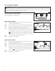
Indoor and 240 VAC Outdoor Models
Indoor models and the 240 VAC Outdoor model will be pre-wired with a power cord
Figure 6
ready to be plugged into a wall power socket.
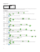
110 VAC Outdoor Models
Step 1 – Route power and ground wires from a power source through a conduit
Figure 7
#MBDL White (SFFO
7"$0VUEPPS.PEFMT
and into the EVOLUTION
TM
cabinet.
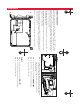
Step 2 – Open the EVOLUTION
TM
controller and access the internal components.
Step 3 – Remove the power compartment cover to access the transformer wiring.
Remove 1/2" (12.7mm) of insulation from the wire ends.
Step 4 – Using the provided wire nuts, secure the transformer Line (black) wire
to the black power source wire, Neutral (white) to the white power source
wire and Equipment Ground wire (green) to the green power source wire.
Note: Earlier EVOLUTION
TM
model is equipped with two Equipment
Ground wires (green). Connect both wires to the green power source wire.
Step 5 – Install and secure the power compartment cover.
Step 6 – Apply power to the controller.
220 VAC Outdoor Models
Step 1 – Route power and ground wires from a power source through a conduit
Figure 8
#SPXO (SFFO:FMMPX #MVF
(L) (N)
(
)
7"$0VUEPPS.PEFMT
and into the EVOLUTION
TM
cabinet.
Step 2 – Open the EVOLUTION
TM
controller and access the internal components.
Step 3 – Remove the power compartment cover to access the transformer terminals.
Step 4 – Remove 1/2" (12.7mm) of insulation from the power source wire ends and
install the brown wire into the Line (L)terminal. Install the green wire into
the Ground (
) terminal and the blue wire into the Neutral (N) terminal.
Step 5 – Install and secure the power compartment cover.
Step 6 – Apply power to the controller.