
User manual


Reelmaster 7000 Hydraulic SystemPage 4 -- 77
IMPORTANT: Use caution when clamping gear
pumpinaviseto avoiddistortinganypumpcompo-
nents.
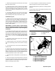
3. Secure the front cover ofthe pump in a vise with the
drive shaft pointing down.
4. Loosenthefour(4)capscrewsthatsecurepumpas-
sembly.
5. Remove pump from vise and remove fasteners.
6. Supportthepumpassemblyandgentlytapthepump
case with a s oft face hammer to loosen the pump sec-
tions. Be careful to not drop parts or disengage gear
mesh.
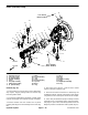
IMPORTANT: Mark therelativepositions ofthegear
teeth and the thrust plates so they can be reassem-
bledinthesameposition.Donottoucht hegearsur-
faces as residueonhands may be corrosive to gear
finish.
7. Removethethrustplatesandsealsfromeachpump
section. Before removing each gear set, apply marking
dye to mating teeth to retain ”timing”. Pump efficiency
maybeaffectediftheteeth arenotinstalled in thesame
positionduringassembly.Keepthepartsforeachpump
section together; do not mix parts between sections.
8. Clean all parts. Check all components for burrs,
scoring, nicks and other damage.
9. Replace the entire pump assembly if parts are ex-
cessively worn or scored.
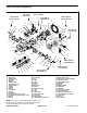
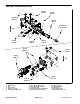
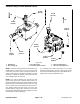
Assembly (Fig. 53)
1. Apply clean hydraulic oiltoallpump parts beforeas-
sembling.
NOTE: Pressure seals and back--up gaskets fit in
grooves machined into thrust plates. Body seals fit in
grooves machined in body faces.
2. Assemble pumpsectionsstartingatfrontcoverend.
Apply grease or petroleum jelly to new section seals to
hold them in position during gear pump assembly.
3. Afterpumphasbeenassembled,tightencapscrews
and nuts by hand. Rotate the drive shaft to check for
binding. Protect the shaft if using a pliers.
4. Tighten the four (4) cap screws evenly in a crossing
pattern to a torque of 33 ft--lb (45 N--m).
Hydraulic
System