
User manual


Reelmaster 7000Page 5 -- 16Electrical System
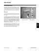
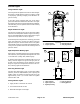
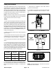
Cutting Unit Position Sensor
Thecuttingunitpositionsensorisanormallyopenprox-
imity sensor that is located on the front carrier frame
(Fig. 13). The sensing plate that closes the sensor is a
gusset on the front right cutting unit (#5) lift arm.
Whenthecuttingunitsarelowered,thegussetonthelift
arm is located near the position sensor and the sensor
closes.ThisclosedsensorprovidesaninputfortheTEC
controller to allow the lowered cutting units to operate.
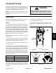
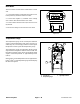
Adjustment
The gap between the cutting unit position sensor and
theliftarmgussetshouldbe0.063”(1.6mm).Ifdistance
isincorrect,loosenjamnutsthatsecurepositions ensor
to bracket. Adjust sensor location withjamnutstoallow
correct gap between sensor and lift arm gusset. Jam
nuts should be torqued from 162 to 198 in--lb (18.4 to
22.4N--m).Afterjamnuts aretightened,makesurethat
gap has not changed.
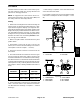
The vertical location of the cutting unit position sensor
on the sensor bracket will determine the turn--around
position of the cutting units. Raising the sensor on the
bracket will allow a higher turn--around position of the
cuttingunits.Loweringthesensoronthebracketwillal-
low a lower turn--around position of the cutting units.
After adjustment to the position sensor, use the Diag-
nostic Display (see Special Tools in this chapter) to
verify that cutting unit position sensor and circuit wiring
arefunctioningcorrectly(seeCuttingUnitPositionSen-
sor in the Component Testing section of this chapter).
1. Position sensor
2. #5 lift arm
3. Gap
Figure 13
1
2
3
1. Position sensor
2. Sensor bracket
3. Screw (2 used)
4. Jam nut (2 used)
5. Lock washer (2 used)
6. Front carrier frame
Figure 14
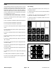
LED location
FRONT
2
3
1
4
5
6