
User manual


Reelmaster 7000 Page 5 -- 21 Electrical System
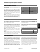
PTO Switch
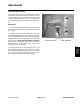
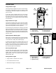
ThePTOswitchislocatedonthe console arm (Fig. 23).
The PTO switch is pulled up to engage the PTO and
pushed in to disengage the PTO.
NOTE: To engage the PTO, the seat has to be occu-
pied, traction speed has to be in low range (4WD) and
the cutting units have to be fully lowered.
Testing
1. Before disconnecting the PTOswitchfortesting,the
switch and its circuit wiring should be tested as a TEC
input with the Diagnostic Display (see Diagnostic Dis-
playintheTroubleshootingsectionofthischapter).Ifthe
Diagnostic Display verifies that the PTO switch and cir-
cuit wiring are functioning correctly, no further switch
testingisnecessary.If,however,theDisplaydetermines
that the PTO switch and circuit wiring are not function-
ing correctly, proceed with test.
2. Make sure ignition switch is OFF. Remove key from
ignition switch.
3. Disassemble console arm to gain access to PTO
switch (see Console Arm Disassembly in the Service
and Repairs section of Chapter 7 -- Chassis).
4. Disconnect harness electrical connector from the
PTO switch.
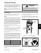
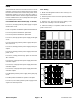
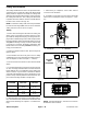
5. Theswitchterminalsare markedasshowninFigure
24. The circuit logic of the PTO s witch is s hown in the
chartbelow.Withtheuseofamultimeter(ohmssetting),
thes witchfunctionscanbetestedtodeterminewhether
continuityexistsbetween thevariousterminalsforeach
switch position. Verify continuity between switch termi-
nals. Replace switch if testing identifies that switch is
faulty.
SWITCH
POSITION
CLOSED
CIRCUITS
OPEN
CIRCUITS
OFF (DOWN) COM B + NC B
COM C + NC C
COM B + NO B
COM C + NO C
ON (UP) COM B + NO B
COM C + NO C
COM B + NC B
COM C + NC C
6. If PTO switch tests correctly and circuit problem still
exists, check wire harness (see Electrical Schematics
and Wire Harness Drawings in Chapter 9 -- Foldout
Drawings).
7. After testingis completed, connect the wireharness
connector to the PTO switch.
8. Assembleconsolearm (seeConsoleArmAssembly
intheService andRepairssectionof Chapter7 -- Chas-
sis).
1. Console arm 2. PTO switch
Figure 23
1
2
1. COM B terminal
2. NO B terminal
3. NC B terminal
4. COM C terminal
5. NO C terminal
6. NC C terminal
Figure 24
2
3
1
6
4
5
Electrical
System