
User manual


Reelmaster 7000 Hydraulic SystemPage 4 -- 23
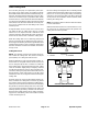
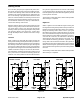
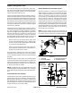
Steering Circuit
A four section gear pump is coupled to the piston (trac-
tion)pump.Thegearpump sectionP3supplieshydrau-
lic flow to the steering control valve and the lift control
manifold. Gear pump hydraulic flow is delivered to the
two circuits through a proportional flow divider located
in the fan control manifold. The steering circuit receives
priority flow from the flow divider. Steering circuit pres-
sure is limited to 1050 PSI (72 bar) by a relief valve lo-
cated in the steering control valve.
With the steering wheel in the neutral position and the
engine running, pump section P3 flow enters the steer-
ing control valve at the P port and goes through the
steeringcontrolspoolvalve,bypassingtherotarymeter
and steering cylinder. Flow leaves the control valve
through the PB port to the oil filter and traction charge
circuit.
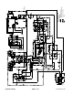
Left Turn
When a left turn is made with the engine running, the
turningofthesteeringwheelpositionsthespoolvalveso
thatflowgoesthroughthetopofthespool.Flowentering
thesteering control valve at the P port goes throughthe
spool and is routed totwoplaces.First,most of the flow
throughthevalveisbypassedoutthePBportbacktothe
oil filter and traction charge circuit. Second, theremain-
deroftheflowis drawnthroughtherotarymeterandout
the L port. Pressure contracts the steering cylinder for
a left turn. The rotary meter ensures that the oil flow to
the cylinder is proportional to the amount of the turning
on the steering wheel. Fluid leaving the cylinder flows
backthroughthespoolvalvethenthroughtheTportand
to the hydraulic reservoir.
Thes teeringcontrolv alvereturnstotheneutralposition
when turning is completed.
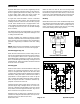
Right Turn
When a right turn is made with the engine running, the
turningofthesteeringwheelpositionsthespoolvalveso
thatflowgoesthroughthebottom of the spool.Flowen-
tering the steering control valve at the P port goes
throughthespoolandisroutedtotwoplaces.Asinaleft
turn, most ofthe flow throughthe valve is bypassed out
the PB port back to the oil filter and traction charge cir-
cuit. Also like a left turn, the remainder of the flow is
drawn through rotary meter but goes out port R. Pres-
sure extends the steering cylinder for a right turn. The
rotary meter ensures that the oil flow to the cylinder is
proportionaltothe amountoftheturningonthesteering
wheel.Fluidleaving thecylinder flows back through the
spool valve then through the Tport and tothe hydraulic
reservoir.
Thes teeringcontrolv alvereturnstotheneutralposition
when turning is completed.
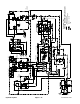
Figure 16
RIGHT TURN
STEERING
CONTROL
VALVE
STEERING
T
L
R
PPB
1050
PSI
6.1
CYLINDER
STEERING
T
L
R
PPB
1050
PSI
6.1
CYLINDER
NEUTRAL POSITION
STEERING
CONTROL
VALVE
STEERING
T
L
R
PPB
1050
PSI
6.1
CYLINDER
STEERING
CONTROL
LEFT TURN
VALVE
NO CYLINDER
MOVEMENT
Hydraulic
System