TM Network VP 3.00 Satellite User’s Guide • 16 to 64 stations in eight-station increments • Field programmable for future upgrades • Does not require EPROM(s) replacement • Operates as a stand-alone controller or under the management of a central computer.
Index Radio Specifications - - - - - - - - - - - - - - - - - - - - - - - - - - - - - - 3 Fuse and Circuit Breaker Specifications - - - - - - - - - - - - - - - 3 Satellite Controller Specifications - - - - - - - - - - - - - - - - - - - - 3 Introduction - - - - - - - - - - - - - - - - - - - - - - - - - - - - - - - - - - - - 4 Modes of Operation - - - - - - - - - - - - - - - - - - - - - - - - - - - - - - - 4 General Editing - - - - - - - - - - - - - - - - - - - - - - - - - - - - - - - - - -
Radio Specifications Equipment Type – Data radio, MAXON, model SD-125 U2 Frequency Band – UHF RF Output Power – 2.0 watt Current Consumption: Standby (Muted) – < 65 mA Transmit 2 watts RF power – < 1.0A FCC License: FCC ID# MNT-PC-UC Fuse & Circuit Breaker Specifications Power Supply: 1.5A On/Off Switch/Circuit Breaker – Main Power Input 3.2A Fuse (Slow-Blow) – Field Output 4.0A Circuit Breaker – Control Functions (Timing Mechanism) Output Board : 3A Fuse Communication Board : 0.
Introduction The Toro Network VPTM Satellite combines modular flexibility, ease of use and increased programmability in a single controller. Modularity means flexibility. The Network VP is available from 16 to 64 stations, and can expand in eight-station increments to meet your needs. Optional station switch capability and surge protection provide simple operation and added security.
Timing Mechanism Components 1 2 Left and Right Arrows allow you to select the next entry field within the same menu line. Any changes will be saved after you exit that entry field. Up and Down Arrows allow you to scroll up and down through the menu items. 3 Operation Mode LED Display will indicate the current satellite operation mode.
Distribution Board Components 4 3 1 2 5 6 1 5V, 9V and 12V LED Indicator - When illuminated, the LED indicates the presence of the corresponding voltage in the satellite’s circuitry. 2 GND, 12V, 9V and 5V Sources - Voltage source pins provide terminals for monitoring the satellite’s internal voltages with the use of a digital multi-meter or an oscilloscope. 3 Timing Mechanism Cable Socket - VP Timing Mechanism data cable connection socket. 4 Data Cable Socket - (For future use.
Pump / Common Board Components 1 Pump Terminal Switch - The Pump terminal can be placed in ON, OFF or Auto with this switch. PUMP 2 Common Terminal Switch - The Common terminal can be placed in ON, OFF or Auto with this switch. COMMON ON OFF AUTO 1 PUMP PUMP COMMON ON COMMON OFF AUTO Note: The Common switch must be set to ON when activating a station using the output board station switch.
Power-Up Diagnostics Upon power-up, the satellite will display: Network VP Booting The Network VP Satellite will initiate a diagnostic test automatically during power-up. This function will take approximately ten seconds and it can not be bypassed. If a problem is detected during the diagnostic test, it will be indicated on the display. These status information can not be edited.
If the satellite has an active running program, the display will read: Sun 04/02/06 02:31 pm Sat# 001-001 Sec: 57 Running 04 prg+ Man (Running Multi-Manual) P01 Sta01 %00:05:00 P01 Sta02 00:05:00 P01 Sta03D 00:05:00 P02 Sta10P 00:05:00 P03 Soak04 00:00:32 GMM Sta35 00:15:00 Man Sta21 00:10:00 Man Sta22S 00:10:00 (The “%” symbol before the runtime indicates that station 01 is percent adjusted.
Pause / Resume Key The Pause command is used to suspend active program or manual irrigation. The Pause function allows the user to specify the pause duration. Pause / Resume Function Directions Pause function example: Program 01 has been manually activated. Pause program 01 for 30 minutes. 1. Press the Pause key. 2. Use the Input Dial to select All, M-Man or Prg:XX (XX = the program number).
Pause All All currently running programs, multi-manual and syringe will be suspended until the pause time-out expires. New start is allowed only for Manual functions. Additional programs that are scheduled to start while Pause All is in effect will be stacked until the Pause time-out expires. Pause All Timed out All activity delayed by Pause All function will resume. Programs and Manual functions that were paused after the Pause All function will resume when their pause time-out expires.
Satellite Settings Satellite Settings allows you to set satellite parameters such as Time, Date and Language. Use the Up or Down Arrows to navigate through the menus. Use the Left and Right Arrow Use the Input Dial to advance to the next entry field on the same menu line. to select values when editing. Comm Mode: – Use this menu item to select the satellite mode of operation between Central, Local or Off mode.
Setup Amps: – Use this menu item to establish and update each of the stations’ nominal current value to the satellite’s memory. These values are used by the satellite for Current Reaction Management (CRM) and Current Prediction Management (CPM). CRM allows the Network VP 3.0 to react to an out-of-tolerance current condition. This condition occurs when a station’s electrical current exceeded the boundaries of the tolerance setting for that station. CPM enables the Network VP 3.
Station Settings Station Settings allows you to set parameters specific to each station. Use the Up or Down Arrows to navigate through the menus. Use the Left and Right Arrow Keys Use the Input Dial S01 – to advance to the next entry field on the same menu line. to select values when editing. Select the station you want to edit in this field. Choose from Station 01 through the satellite maximum station count of 64.
Edit Name: – Use this menu item to assign a name description to the station. The naming format is XX-AAYYY, where XX represents the golf course hole number, AA represents the area description acronym and YYY represents the sprinkler number within the area. By following the naming format, you can easily figure out where and what area the station is watering.
Scheduled Watering The Network VP satellite features 64 fully-independent resident programs. With three types of programs to select from, you can further custom fit your irrigation programs to any landscape. • Basic Irrigation Program will activate a station or group of stations with one start time on a daily basis. Each station will water for the duration specified in hours, minutes and seconds.
Basic Irrigation Program Setting: Basic Irrigation Program example: Create Program 01 with stations 1–5 for 25 minutes each and stations 11–20 for 15 minutes each with a program adjustment of 110%. Set the start time at 6:30 am with five maximum simultaneous active station. 1. Press the Scheduled Watering Key Input Dial . The cursor is initially located at the program selection field. Use the to select the program (P01–P64) you want to create or modify. For this example, select program 01. 2.
Advanced Irrigation Program Setting: Advance Irrigation Program example: Create program 2 with stations 6–10 for 15 minutes each with no percent adjustment. Set the start time 01 at 5:45 am every Monday, Wednesday and Friday only. Set the maximum simultaneous active station to 5. 1. Press the Scheduled Watering Key Input Dial . The cursor is initially located at the program selection field. Use the to select the program (P01–P64) you want to create or modify. For this example, select program 02. 2.
13. Press the Right Arrow to advance the cursor to the next entry field. This entry field will indicate the runtime in hours, minutes and seconds ( HH:MM:SS). Use the Input Dial and the Right Arrow Key to select the appropriate runtime value. For this example, set the value to 00:15:00. 14. Press the Down Arrow to advance the cursor to the Simult: field. Use the Input Dial to select the maximum allowable simultaneous active station. For this example, set the value to 05.
7. Press the Down Arrow to advance the cursor to the Delay: field. This delay time will determine the wait time between program cycles. Use the Input Dial and Right Arrow Keys to select the delay time value. Use the Left to navigate between the Hours and Minutes fields. For this example, set the delay time to 02:15. 8. Press the Down Arrow to advance the cursor to the Sta#: field. Use the Input Dial to select the correct value of the first station being irrigated.
5. Press the Down Arrow to advance to the Sta field. Use this field to enter the station numbers that corresponds to the currently displayed sequence. Use the Right and Left arrows between the station number fields. Use the Input Dial to navigate to select station number. Set Stations 01, 05, 07 and 09 to sequence 01. Repeat Steps 4 and 5 to set additional sequences. Set a 20-minute station runtimes to sequence 02. Set stations 02, 03, 04, 11, 12 and 13 to sequence 02.
Manual Watering The Manual Watering functions are used for additional watering if the irrigation program is not sufficient. They can also be used to troubleshoot each station for proper operation. Pressing the Manual Watering Key will access three manual irrigation functions; Multi-Manual, Syringe and Program. M-Manual - Select M-Manual to activate a station or group of stations with a specified runtime.
Syringe - Choose Syringe to activate all the stations in a selected irrigation program for a specified runtime. Note: The Maximum number of simultaneous stations set in the program still applies. Manual Syringe Activation Directions Syringe activation example: Manually activate all the stations in Program 3 for 2 minutes each. Note: An irrigation program must be configured to activate Manual Syringe. 1. Press the Manual Watering Key . 2. The cursor should be located in the Manual field.
% (Percent) Adjust The percent adjust function allows you to fine tune irrigation programs. With weather conditions changing constantly, Percent Adjust allows you to tune your system easily without changing all the values in the program. % Adjust Directions 1. Press the % Adjust Key . The cursor is initially located at the Satellite % Adjust field. Use the Input Dial to adjust the satellite watering up to 900% or down to 1%.
Menu: Station Amps – Use this menu item to review each of the station’s last recorded voltage amperage, nominal amperage value, tolerance value, alarm events, pump nominal amperage value. Use the Input Dial available stations. Use the Down arrow to scroll through the to scroll down to the data fields. You can reset the Nominal amperage value within this menu item by selecting Reset using the Input Dial and pressing the Down arrow to activate.
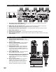
PUMP COMMON ON OFF AUTO PUMP COMMON Troubleshooting Guide Power Transformer Pump Common Board AC Power Terminals WARNING HIGH VOLTAGE 1 2 Station Output Board 6 115V 1 4 3 7 5 4 A M P Electrical Protection 1 - Main Power Switch / 1.5A Circuit Breaker - Protects the controller from a short circuit on the incoming power line. 2 - Input Voltage Select Switch - Set the input power supply to 115 VAC or 230 VAC 3 - 3.
14 PUMP Power Distribution Board 18 COMMON ON OFF AUTO PUMP 15 COMMON 10 19 20 11 Station Output Board 12 13 16 21 DS2 22 23 24 PUMP COMMON ON OFF AUTO DS3 DS4 DS5 25 PUMP COMMON 1 5V 9V 12V 17 Indicators Pump Relay LED Indicator - When illuminated, the pump relay is activated. Common Relay LED Indicator - When illuminated, the common relay number 1 is activated. Common Relay LED Indicator - When illuminated, the common relay number 2 is activated.
Lithium Battery Replacement Procedure WARNING! DANGER OF EXPLOSION IF BATTERY IS INSTALLED INCORRECTLY. REPLACE ONLY WITH THE SAME OR EQUIVALENT TYPE OF BATTERY. ALWAYS DISPOSE OF USED BATTERIES ACCORDING TO THE MANUFACTURER’S INSTRUCTIONS. A 3.9V Lithium battery (P/N 363-2200) is installed behind the timing mechanism circuit board to sustain the controller’s time and date for approximately 10 years without any additional power. 1. Place the controller’s power switch to OFF. 2.