
Service Manual
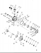
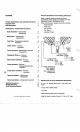

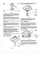

Motor
Rotor
Pump
Rotor
Spring
Fig.
17
27
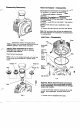
Inspect the rotor assemblies. Remove the piston
balls from the rotor, one at a time, by working clockwise
from the letter stamped in the face of the rotor and
placing
in
a prepared container.
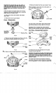
31
Remove the snap ring that retains the output shaft
and tap or press the shaft from the body.
Body
Seal
Bearing
Retaining
Ring
Note:
Each ball must be replaced in the same bore Fig.
19
from which it was removed. Use a suitable container for
piston ball storage such as an egg carton or ice cube
32
Remove the large retaining ring that retains the
tray. output bearing to body. Drive or press the output
28
Inspect for broken or collapsed springs in the motor
rotor assembly.
Cover-
Reassembly
Note:
When broken or collapsed springs are found with
33
Inspect cover assembly, especially around the
no other irregularities, the springs may be replaced
control shaft area. Replace the cover assembly
if
'it is
individually without replacing the complete motor rotor
broken, cracked or
if
side clearance between control
bearing and seal from the motor body.
assembly. shaft and cover exceeds
.006.
29
Inspect the piston balls. They must be smooth and
completely free of any irregularities.
30
Inspect the rotor bores, rotor bushing and pintle
journals for irregularities or excessive clearance. The
ball piston
to
rotor bore clearance is select fit
electronically to
.0002
to
.0006
of an inch. When
irregularities or excessive clearance are noted, replace
the complete rotor assembly.
Install ball pistons in their matching bores. Hold them in
place with a rubber band.
Body
Body
output
Shaft
34
In most cases, it
will
not be necessary to remove
the control shaft from the cover.
If
the dowel is loose
or
broken in the control shaft, remove the shaft using the
following procedures.
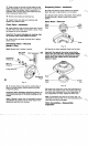
9
Measure this Distance
A
Control
9
Fig.
20
35
Measure the distance between center of dowel pin
and the end of the shaft as shown in Figure
20.
36
Turn cover over. Use this dimension to locate dowel
pin
in
cover face. Drill
11/32”
diameter hole at center
point of dowel pin. Drill hole exactly in line with center
of shaft.
Fig.
18