
Service Manual


Note:
Do
not force pintle through the pump rotor
assembly as it is a slip fit. The pump rotor assembly
must turn freely on the pintle by hand.
If
not recheck
pintle installation.
50
Push dump valve shaft in and thread into dump
valve bracket.
Torque to
2-3
Foot Pounds.
Retaining
51
Lightly grease new cover sealing ring and install in
the groove in the cover.
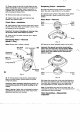
Body-Reassembly
Lip Seal
Fig.
34
54
Install output shaft bearing by positioning bearing
over output shaft and pressing on outer race of ball
bearing to the bottom position in body.
55 Install small snap ring on output shaft against inner
bearing race.
Body
Fig.
32
52
Lubricate inner surface of new lip seal and install
with the rubber lip
of
the seal toward the counter bore
in body.
Important:
Do
not over press
or
drive the
seal,
this
may damage the rubber sealing portion
of
the seal
or
distort counter bore.
53
Install output shaft into body, protecting the shaft
seal lip from keyway and snap ring grooves.
Support the output shaft from underneath body
so
that
the cross pin in output shaft is tight against body.
Use a solid block (steel or hardwood)
2
inches in
diameter by at least
1%
inches long to support the
output shaft.
56 Install the large retaining ring used to retain ball
bearing in body.
Note:
The output shaft must rotate freely by hand.
If
it
doesn't, recheck bearing installation.
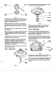
Motor Rotor-Installation
Motor
Wide
Rotor Rubber
Assy. Band
I
a
12
Fig.
35
57
Align the slot in the motor rotor assembly with the
cross pin on the output shaft and install the motor rotor
in
body.
58
Remove the rubber band retaining the ball pistons
in their respective bores (if used).
Fig.
33