
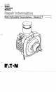
Service Manual


Important:
Do
not allow the cam ring, pintle, or
9
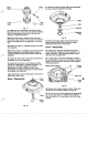
Remove the button from the cover (model
7
only).
pump rotor assembly to
lift
with the cover. The
pump ball piston assembly must remain intact
as
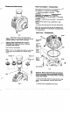
Where applicable, remove the dump valve guide, nut,
the ball pistons are matched to the pump rotor and O-ring. Discard the O-ring.
bores.
Cove
If
the cover does not separate easily from the body
because of fluid seal, tap the body and or cover with
plastic hammer to break the seal.
5 Remove the dump valve bracket, and springs,
when used.
6
Remove the seal ring and discard.
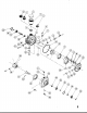
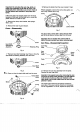
Cover-Disassembly
and Bearing
Assembly Retaining Ring
Fig.
4
7
Remove input shaft retaining ring. Press or drive the
input shaft and bearing assembly from the cover.
Cover
Input Shaft
I
Seal
Fig.
5
6
8
Press or drive the input shaft seal from the cover.
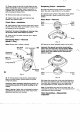
Dump Valve
Guide
Butt
Fig.
7
10
Use a sharp, narrow tool to pierce the top metal
part of the oil seal and remove seal from the cover.
Important:
Do
not scratch
the
control shaft or
distort the seal counter bore when removing seal.
Cam
Ring-Disassembly/lnspection
Cam Ring
Assy.
Cam
Pintle
Body
Fig.
8
11
Remove the cam ring assembly from the pintle.
Remove the cam ring insert.
Important: Use special care when removing the cam
ring
from the pump rotor assembly. The ball pistons
must remain
in
place as they are matched to the
rotor bores. Use a wide rubber band to hold the ball
pistons
in
place.
12 Inspect area where the ball pistons contact the
pump race. This area must be smooth and completely
free of irregularities.
If
it is not, replace the pump race.