
User's Manual
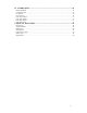
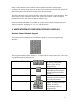


Other visible elements of the satellite control module include the radio antenna
connector, the station output ports (up to four 15-pin connectors), and the red “power on”
light, all located on the bottom front side of the control module.
The back side panel of the control module is where the serial port (9-pin connector), data
retrieval port (9-pin connector) and two fuse sockets are located. A red LED light is
provided next to the fuse socket to indicate a blown fuse.
Sentinel satellite controllers are available in various station output configurations in 12-
station increments, including 12-, 24-, 36-, and 48-stations.
II. USER INTERFACE OVERVIEW (KEYPAD & DISPLAY)
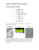
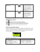
Sentinel Control Module Keypad
The Sentinel Control Module has a 24-button keypad for use as the programming
interface:
This keypad includes numeric buttons 1 – 9 and 0 used for numeric data entry. Also used
in programming and operations are:
ON/YES & OFF/NO Keys
Used for manual operations
as well as entering ON /
OFF or YES / NO in
programming.
ESC (Escape) Key
Used for exiting menus or
Edit Mode and returning to
normal operations (default
screen)
ENTER Key
Used for functions like
entering a selected submenu
or saving information.
Arrow (Navigation) Keys
Used for navigating in
Menus, Submenus, and Edit
Modes, as well an
incrementing values in
programming.
5