
Installation Instructions


Introduction
The Field Interface Unit (FIU) provides the communications hardware link between the SitePro
TM
central computer, the SitePro
compatible field satellite controllers and the SitePro Central Decoder System components. The FIU is available in four configu-
rations to provide various combinations of wireline and radio communication paths. An auxiliary port is provided on all FIU
models for switch-type sensor input.
The FIU enclosure is designed for installation in a climate-controlled environment, next to or near the central computer, with a
maximum separation distance of 50' (15.2 m). Power for the FIU is provided by a 100–240 V a.c./12 V d.c. 50/60 Hz power
supply adaptable to both domestic and international plug receptacles. A lighted On/Off rocker switch located on the front of the
FIU controls power to the unit and is circuit-protected with a 1.5 amp fast-blow fuse. An array of indicator lights on the front
panel is provided for visual confirmation of system communication activity.
The following instructions cover installation of the Field Interface Unit (FIU), Surge Protection Unit (SPU), Duplex Modular Wall
Plate, optional Radio-Link components and optional SitePro Central Decoder System (CDS) components. For Network CDS
system installation, additional detailed installation information is provided with the Network CDS Decoder Interface Unit (DIU).
IMPORTANT: For your safety and equipment protection, please comply with all Caution and Warning statements
within this document. It is the responsibility of the installer to comply with all NEC and/or local electrical codes that
apply to the installation of this equipment. Please refer to page 16 for FCC and CISPR 22 information.
Note:
Some cabling and hardware components are provided for installation of the FIU, Surge Protection Unit (SPU) and
duplex modular wall plate. All other materials; i.e., wire, conduit, grounding conductors, communication cable, radio(s) and
related radio hardware must be purchased separately.
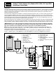
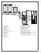
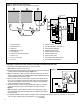
The diagrams on pages 1–5 depict the various FIU model system configurations. See
Figures 1 and 5 for model 2010
(Figure 1 - Satellite, Figure 5 - CDS), FIgure 2 for model 2020, Figure 3 for model 2011 and Figure 4 for model 2021.
SitePro
TM
Field Interface Unit, Models 2010, 2020, 2011 and 2021
Installation Instructions
13
16
12
14
15
CH 2
CH 3
CH 1
+12V DC
11
10
9
17
7
8
1
3
6
5
4
13
AUX
16
2
Figure 1 - Model 2010 (one wireline port)
1 - Field Interface Unit
2 - 12 V d.c. Power Jack
3 - Power Adapter
4 - Central Computer
5 - COM Port 1
6 - DB-9/DB-9 Serial Cable
7 - Channel 1 (in)
8 - COM Line 1 (out)
9 - RJ11 Modular Cable
10 - Duplex Modular Wall Plate
11 - Shielded Interface Cable
12 - Surge Protection Unit
13 - Communication Cable
14 - Satellite Controller
15 - Communication Cable - COM Path 1
(out to satellites)
16 - Auxiliary Port (optional for sensors)
17 - 1.5A Fuse
50' (15.2 m)
max.