
Installation Instructions


7. A 25' (7.6 m) length interface cable is supplied for the connection of the modular wall plate to the SPU. Select an installa-
tion site for the SPU on an outside wall, within the cable reach, and 3' to 5' (0.9 m to 1.5 m) above ground level for straight
and easy access to an earth ground. Attach the SPU securely to the wall using appropriate fasteners inserted through the
four mounting holes provided in the SPU enclosure.
8. Install 3/4" (19 mm) EMT conduit from the duplex junction box to the bottom left side of the SPU enclosure.
9. Pull the interface cable through the conduit from the duplex junction box into the SPU.
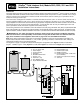
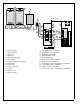
10. Secure the black and white wire pair(s) to the modular wall plate receptacle and the SPU as shown in
Figure 7.
Note: Connections for two wireline communication paths are shown. If only one path is required, tape back the unused
wire pair for future use.
Note: The drain wire is connected to the last terminal position on the central side of the SPU and clipped flush with the
cable outer insulation at the wall plate receptacle.
11. Secure the modular wall plate receptacle to the junction box. Connect the FIU to the modular wall plate receptacle using
the RJ11 modular cable(s) supplied.
12. Route the communication cable(s) from satellite or DIU into the SPU and connect wires as shown in
Figure 7.
Note: The communication cable drain wire(s) can be connected to terminals 3, 6, 9 or 12. These terminal positions are all
connected to the ground plane.
Earth Ground Installation
Important Notice To Installer: It is recommended that the electrical grounds for the central computer, FIU and SPU are
bonded together to achieve the same grounding potential. This is especially important for installation sites located in lightning-
prone regions. In addition, using a power strip or UPS with surge protection for the central computer and FIU is also recom-
mended.
The Surge Protection Unit must have an efficient pathway to earth ground. A 6 AWG (10 mm
2
) bare copper ground wire con-
necting the SPU ground lug to the earth ground device(s) must be installed in the most direct path as possible, avoiding sharp
bends. Resistance in the ground path (when measured with an earth ground resistance test device) must be within the follow-
ing tolerances: 0 to 10 ohms – excellent, 11 to 20 ohms – acceptable, 21–30 ohms – marginal.
The following instructions describe one of several acceptable grounding methods. Due to variables in soil composition, the
ground-rod method described may not be suitable for your installation site. Copper plate(s) or other grounding devices may be
required to achieve the required resistance level necessary for proper grounding protection. Recommended earth ground
resistance instruments are: AEMC Instruments, model 3710 clamp-on tester, or Biddle Megger, model 250260. Contact your
local Toro distributor for assistance in acquiring this test equipment.
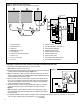
GROUND
HERE
Figure 7
Green
Shielded Interface Cable
Shielded Communication Cable
Note: In lightning-prone
areas, additional surge
protection is recommended
and can be easily added to
the SPU by installing the
SPU accessory kit,
P/N 102-0767.
Red
Junction Box
Wall Plate Assembly
Drain
Path 1
Path 1
Path 2
Path 2
Path 1
Path 2
6
Yellow
Gray
Drain