
Installation Instructions


Procedure
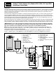
1. Drive a 5/8" (16 mm) by 8' (2.5 cm) copper-clad steel
ground rod into well-moistened soil not more than
8' (2.5 cm) from the SPU. The top of the ground rod
should be 12" (30.5 cm) below grade level.
2. Install 3/4" (19 mm) conduit from the bottom of the SPU
enclosure to approximately 12" (30.5 cm) below grade
level. Use a 90° sweep elbow with a minimum radius of
8" (20.3 cm) at the end of the conduit.
3. Using a clamp or “Cad weld” fastener, attach a length
of 6 AWG (10 mm
2
) solid copper wire near the top of
the ground rod. Avoiding sharp bends, route the wire
through the conduit into the SPU. Secure the wire to
the large copper ground lug provided. See
Figure 8.
4. To eliminate ground differential, attach the computer
and FIU power source equipment ground to the SPU
ground device.
Note: Make sure the soil surrounding the ground rod(s)
remains well moistened at all times. The addition of
some form of irrigation may be required if the SPU is
installed in a non-irrigated location.
5. Measure the ground resistance per the instructions pro-
vided with the ground test instrument. If the resistance
exceeds the acceptable limit, additional ground rod(s)
can be installed at a distance equal to twice the buried
depth of the first rod; i.e., 16' (4.9 m). Interconnect the
ground rods using #6 (10 mm
2
) solid copper wire and
test again. If the measured ground resistance continues
to read above the acceptable limit, contact your local
Toro distributor for further assistance and recommenda-
tions.
6. Install a valve box over the ground rod to provide access to the ground wire connection(s).
Satellite Communication Cable Installation
Please note the following communication cable installation
requirements and suggestions:
• The satellite is designed for use with shielded, twisted-
pair, communication cable. Consult with your local Toro
distributor for the cable type and wire size best suited
for your installation.
• More than one cable run can be routed from the SPU.
• A branch communication cable can be routed from
another satellite connection.
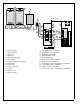
• If additional cable runs are installed for future system
expansion, the end of each cable run must be terminat-
ed with a 620 ohm resistor. See inset in Figure 9.
• If the communication cable is routed in the same trench
as main power wires, a minimum of 12" (30.5 cm) sepa-
ration is recommended to prevent voltage induction on
the communication cable. Check local codes for actual
requirements.
• If in-ground cable splices or repairs are required, the
connection must be properly insulated with a waterproof
splicing device. Using an appropriate splicing kit, such as Scotchcast 82-A1 (or equivalent), is recommended. Placing the
cable splice in a small valve box for protection and accessibility is also recognized as good
installation practice.
Procedure
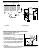
1. Route the communication cable(s) from the SPU to the satellite locations as shown in Figure 9.
2. Connect the communication cable to the satellites per the installation instructions supplied with the satellite controller.
8' to 12'
(2.5 m to 3.7 m)
90°
12"
(30.5 cm)
Figure 8
Valve Box
8" (20.3 cm)
Minimum Radius
Ground Lug
Surge Protection Unit
#6 (10 mm
2
)
Solid Copper Wire
Wires To Additional Ground
Rod and Computer AC
Service Equipment Ground
8' (2.5 m) Copper-Clad
Steel Ground Rod
Figure 9
620 ohm
resistor
SPU
7