
Operation Manual

G014635
1
2
3
g014635
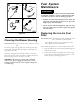
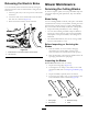
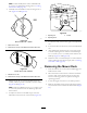
Figure61
1.Frontsupportrod3.Deckbracket
2.Lockingnut
5.Carefullylowerthefrontofthemowerdecktothe
ground.
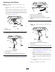
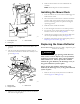
6.Liftthemowerdeckandhangerbracketsclearof
therearliftrodandlowerthemowercarefullytothe
ground(Figure62).
G015338
2
2
3
1
2
2
3
g015338
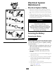
Figure62
1.Mowerdeck
3.Rearliftrod
2.Hangerbracket
7.Slidethemowerdeckrearwardtoremovethemower
beltfromtheenginepulley.
8.Slidethemowerdeckoutfromunderneaththe
machine.
Note:Retainallpartsforfutureinstallation.
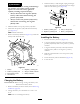
InstallingtheMowerDeck
1.Parkthemachineonalevelsurfaceanddisengagethe
blade-controlswitch.
2.Movethemotion-controlleversoutwardtothePARK
position,shutofftheengine,removethekey,and
waitforallmovingpartstostopbeforeleavingthe
operatingposition.
3.Slidethemowerunderthemachine.
4.Lowertheheight-of-cutlevertothelowestposition.
5.Lifttherearofthemowerdeckandguidethehanger
bracketsovertherearliftrod(Figure62).
6.Attachthefrontsupportrodtothemowerdeckwith
theclevispinandhairpin-cotterpin(Figure61).
7.Installthemowerbeltontotheenginepulley;referto
ReplacingtheMowerBelt(page42).
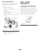
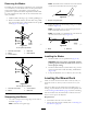
ReplacingtheGrassDeector
ServiceInterval:Beforeeachuseordaily—Inspectthegrass
deectorfordamage.
WARNING
Anuncovereddischargeopeningcouldallowthe
lawnmowertothrowobjectsatyouorbystanders,
resultinginseriousinjury.Also,contactwiththe
bladecouldoccur.Neveroperatethemachine
withoutthegrassdeector,thedischargecover,or
thegrass-collectionsysteminplace.
Neveroperatethemachinewithoutthegrass
deector,thedischargecover,orthegrass-collection
systeminplace.
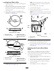
1.Removethenut(3/8inch)fromtherodunderthe
mower(Figure63andFigure64).
40