
Operation Manual


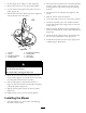

Figure47
1.Cuttingedge3.Wear/slotforming
2.Curvedarea
CheckingforBentBlades
1.Rotatethebladesuntiltheendsfaceforwardand
backward(Figure48).Measurefromalevelsurface
tothecuttingedge,positionA,oftheblades
(Figure48).Notethisdimension.
Figure48
2.Rotatetheoppositeendsofthebladesforward.
3.Measurefromalevelsurfacetothecuttingedgeof
thebladesatthesamepositionasinstep1.The
differencebetweenthedimensionsobtainedinsteps
1and2mustnotexceed1/8inch(3mm).Ifthis
dimensionexceeds1/8inch(3mm),thebladeis
bentandmustbereplaced.RefertoRemovingthe
BladesandInstallingtheBlades.
Abladethatisbentordamagedcouldbreak
apartandcouldseriouslyinjureorkillyouor
bystanders.
•Alwaysreplacebentordamagedbladewith
anewblade.
•Neverleorcreatesharpnotchesinthe
edgesorsurfacesofblade.
RemovingtheBlades
Thebladesmustbereplacedifasolidobjectishit,
ifthebladeisoutofbalance,orthebladeisbent.
Toensureoptimumperformanceandcontinued
safetyconformanceofthemachine,usegenuineToro
replacementblades.Replacementbladesmadebyother
manufacturersmayresultinnon-conformancewith
safetystandards.
Holdthebladeendusingaragorthickly-paddedglove.
Removethebladebolt,curvedwasher,bladestiffener,
andbladefromthespindleshaft(Figure49).
Figure49
1.Rotationaldirectionofright
cuttingblade
6.Fasteningdirection,
counterthreadedbolt
2.Rightcuttingblade
7.Bladebolt,leftcutting
blade
3.Bladestiffener
8.Fasteningdirection,
normalthreadedbolt
4.Curvedwasher9.Leftcuttingblade
5.Counterthreadedblade
bolt,rightcuttingblade
10.Rotationaldirectionofleft
cuttingblade.
SharpeningtheBlades
1.Usealetosharpenthecuttingedgeatbothends
oftheblade(Figure50).Maintaintheoriginalangle.
Thebladeretainsitsbalanceifthesameamountof
materialisremovedfrombothcuttingedges.
36