Toro Modular Controller - 4 to 24 Stations ON PREV NEXT OFF % User’s Guide Installation ♦ Programming ♦ Operation ♦
Introduction The TMC-424E Series takes modularity to a whole new level. Toro’s advanced modular technology combines sophisticated features with simple operation to provide a customizable controller. Station count can be 4 – 24 stations, using four-or eight-station modules. Real-time flow sensing monitors up to three independent sensors and is compatible with the Toro TFS Series flow sensors. Versatile run times allows for additional watering flexibility.
The unique TMC-424E Expansion Modules are color-coded for easy identification. The modules can be mixed and matched in any combination and are available in six models as indicated in the table below.
Table of Contents Introduction . . . . . . . . . . . . . . . . . . . . . . . . . . . . . . . . . . . . . . . . . . . . . . . . . . . . . . . . . . . . . . . . . . ii Control Module Overview . . . . . . . . . . . . . . . . . . . . . . . . . . . . . . . . . . . . . . . . . . . . . . . . . . . . . . . 2 Internal Component Overview . . . . . . . . . . . . . . . . . . . . . . . . . . . . . . . . . . . . . . . . . . . . . . . . . . . 4 Programming Overview . . . . . . . . . . . . . . . . . . . . . . . . . . . . .
Manual Operations . . . . . . . . . . . . . . . . . . . . . . . . . . . . . . . . . . . . . . . . . . . . . . . . . . . . . . . . . . 14 Manual Station Operations . . . . . . . . . . . . . . . . . . . . . . . . . . . . . . . . . . . . . . . . . . . . . . . . . . 14 True Manual Operation . . . . . . . . . . . . . . . . . . . . . . . . . . . . . . . . . . . . . . . . . . . . . . . . . . 14 Timed Manual Operation . . . . . . . . . . . . . . . . . . . . . . . . . . . . . . . . . . . . . . . . . . . .
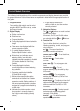
Control Module Overview The following brief descriptions of the controller components and display elements are provided for general overview. Each of these items are explained in detail within the appropriate section of this guide. 1 - Program Switch Four-position slide switch used to select program A, B, C and D for set up, review and manual control. 2 - Digital Display a - Station run time icon. b - Start time icon. c - Program identifiers.
c e d g f h b i a 1 2 l k 3 j ON PREV NEXT OFF 5 % 4 – To operate watering programs manually. manual station – To operate individual stations manually. valve test – To manually test valve operating sequence using a temporary run time. review – To recap all program information including: start times, run times, and season adjust %. OFF – Shuts off and prevents all automatic and manual watering operations.
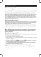
Internal Component Overview 7 11 8 12 9 6 13 10 14 15 17 19 6 - Power supply compartment cover. 7 - Control module ribbon cable receptacle. 8 - Transformer 24 VAC output connection terminals 9 - MR-1 remote connection port. 10 - Rain sensor bypass switch. 11 - Auxiliary port (not enabled). 12 - Flow sensor expansion module (model TSM-8F indicated). 13 - Flow sensor wiring terminals 14 - Flow module master valve wiring terminal. 15 - Expansion module valve wiring terminals.
Programming Overview What is a watering program? In basic terms, a watering program is a small set of instructions that tells the controller which days will be active for watering, when to start a watering cycle, and how long each station will operate during the cycle. The TMC-424E series has four independent watering programs identified as A, B, C, and D.
Controller Programming NOTE: English display prompts and 12-hour (a.m./p.m.) time format are factory-default settings. To select an optional display language, including Spanish, French, Italian, German and Portuguese, and/or a 24-hour time format, refer to the Special Function setup procedures on page 13. Set Current Time and Date Turn the Function Dial clockwise to Current Time/Day . The hour digits will begin flashing. Adjust the display by pressing the or buttons.
Set Program Start Times NOTE: The TMC-424E enables a total of 16 unique start times to assigned to four programs in any combination totaling 16. For example, program A could have 12 start time assignments, which would leave four start time assignments available for programs B, C and D. 1. Turn the Function Dial to Start Times . The start time hour digit(s) will begin flashing. 2. Press the or button to select a start time number (01 to 16).
To Set Calendar Days: 1. Turn the Function Dial to Calendar Days . 2. Sunday will be displayed and selected to water indicated by the water icon. To exclude the day from the schedule, press the or button to display the No Water icon. 3. Press the button to select the next day. 4. Repeat step 2 and 3 to schedule the remaining days of the week. To Set Odd or Even Days: 1. Turn the Function Dial to the Odd/Even position. 2. Press the or button to select ODD or EVEN. 3.
Season Adjust Feature The Season Adjust feature enables the cumulative program run time to be easily increased or decreased by a percentage factor from 0% (Off) – 200%, in 10% increments. Season Adjust can be applied to individual programs and globally to all programs by selected months of the year. When a Season Adjust factor is applied by program and by month, the adjusted program duration is the result of the combined percentage factors.
Special Functions The following program setup options and control parameters are provided in the Special Functions dial position. NOTE: To review the factory default settings for each function, refer to “Appendix D - Controller Default Settings” on page 31.
NOTE: A program must have the MV/PS control option enabled to permit individual stations assigned to the program to be excluded from MV/PS operation. In other words, assigning MV/PS operation by station is not applicable unless MV/PS operation for its assigned program is enabled. • Master Valve/Pump Start Operation by Program 1. Set the Program Switch to select program A, B, C, or D. 2. Turn the Function Dial to Special Functions . 3.
Setting Watering Cycle Repeat Option This option enables a program watering cycle to automatically repeat operation from 1 to 30 times per program start. 1. Set the Program Switch to select program A, B, C, or D. 2. Turn the Function Dial to Special Functions . 3. Press the button as needed to display CYC --N (Cycle [repeat] - No [Off]). 4. Press the 5. Press the or button to select CYC --Y (Cycle [repeat] - Yes [On]). button once to display RPT – – (Repeat (none). 6.
Erase Program Memory Erasing the program memory will remove all user-defined information including run times, start times and day schedule from a specified program. Additionally, all control options specified for the program will be reset to factory defaults. 1. Set the Program Switch to select program A, B, C, or D. 2. Turn the Function Dial to Special Functions . 3. Press the button as needed to display ERASE. 4.
Manual Operations The TMC-424E offers several manual operation methods. A separate Function Dial position is provided for Manual Station and Manual Program operations NOTE: All program control options selected within Special Functions will also apply to all manual control operations.
Manual Program Operations This type of manual watering is also known as “Semi-automatic” operation. When a program is started manually, it runs through the watering cycle as if started automatically. A single program can be operated, or multiple programs can be run in sequence or simultaneously. NOTE: All automatic program control options selected within Special Functions will also apply to all manual operations. • Single Program Operation 1. Turn the Function Dial to Manual Program . 2.
Flow Sensor Operations Flow monitoring is one of the best water resource management tools available in the irrigation industry today. With definable under-, over- and critical-flow limits set, broken lateral or mainline piping, stuck valves or damaged sprinklers can be quickly detected and bypassed automatically. The TMC-424E accepts up to three flow-sensing expansion modules (flow modules) that enable the controller to read, store and compare flow rate data from individual flow meters.
• Select Flow Sensor Module Master Valve Type 1. Press the button to display MV:NC (Master Valve: Normally Closed). If the flow module does not control a master valve, press the button twice to skip this setting. NOTE: When multiple flow sensor modules are installed, the first module in sequence will be selected (designated by the flow sensor icon ). To change the module selection, press the or button. 2.
7. Press the button to select UF -- -- (Under Flow – Off). This setting establishes the alert threshold for a flow rate below the Learned Flow. 8. Press the or button to select a value from 10–100%, (in 10% increments). Select -- -- to disable this threshold. 9. Press the button to select CF -- -- (Critical Flow – Off). This setting establishes the alert threshold for a flow rate above the Learned Flow. 10. Press the or button to select a value from 10–100% (in 10% increments).
Rain Sensor Control by Program This unique TMC-424E feature enables rain sensor control input to be enabled/disabled for specific programs. By default rain sensor input is active for all programs. 1. Turn the Function Dial to Sensors . 2. Set the Program Switch to select program A, B, C, or D. 3. Press the button as needed to select RS(A) - - Y (Rain Sensor [program A] Yes (default). or button to select RS(A ) - - N (Timed Bypass – No). 5. Repeat steps 2–4 for each program as required. 4.
Rain Delay Feature The Rain Delay and Season Adjust control features enable quick, temporary changes in operation to help compensate for changes in weather and season. Rain Delay enables all automatic watering operations to be delayed from 1 to 14 days. For example, rain is forecast in your area for the next two days. Instead of turning the controller off and possibly forgetting to turn it back on, a 3-day delay can be easily set.
Installation Instructions Preparing the Cabinet for Installation 1. Swing open the timing mechanism to access the internal components and wiring access holes. 2. Five wiring access holes are provided in the bottom of the cabinet as follows: A- 1/2" (13mm) for power and equipment ground wires. B- Two 1/2" (13mm) knock-outs for the optional rain sensor or handheld remote wiring. C- Two 3/4" (19mm) 1" (25mm) knock-outs for field wires.
Cabinet Installation 1. Drive a wood screw into the wall within eye level until only 1/4" (10mm) of the screw is exposed. NOTE: If installing the controller on drywall or 7" masonry, install the appropriate type screw (17,78mm) anchors. 2. Hang the cabinet on the screw using the keyhole slot. 3. Open the controller cabinet and swing open the timing mechanism to access the lower mounting screw location. 4. Install the lower mounting screw in the hole provided and tighten securely. 5.
Pump Start/ Master Valve Valve Common Valve Common Wire Pump Start Relay Master Valve CAUTION: To avoid possible equipment damage, do not connect pump starter directly to the controller. A 24V, 0.5A (maximum) relay must be used for this connection. Flow Sensor Connection 1. Route the flow sensor wires into the controller cabinet. 2. Connect the flow sensor wires to the flow-enabled expansion module as follows: Black to negative (–) and Red to positive (+).
Input Power Connection - Indoor Models NOTE: Unlike most indoor-type controller models, the TMC-424E-ID model incorporates an internal transformer. A Class C power cord and strain relief are supplied for connection of the transformer terminal block to a grounded wall outlet. 1. Remove the transformer compartment cover secured by two phillips screws. 2. Referring to the illustration, install the strain relief and tighten securely using appropriate hand tools.
Input Power Connection - Outdoor Models WARNING: AC power wiring must be installed and connected by qualified personnel only. All electrical components and installation procedures must comply with all applicable electrical codes. Some codes may require a means of disconnection from the AC power source installed in the fixed wiring and having a contact separation of at least 0.120” (3mm) in the line and neutral poles. Make sure the power source is OFF prior to connecting the controller. 1.
Rain Sensor Installation (Optional) All Toro rain sensors, including wireless models TWRS and TWFRS (rain/freeze), and wired version TRS, can be connected directly to the TMC-424E to automatically interrupt irrigation when the preset rain or (freeze) threshold is met. A sensor bypass switch is provided to override sensor operation as needed. Refer to page 18 for additional Rain Sensor operating information. When the sensor absorbs moisture, it signals the TMC-424E to suspend automatic watering operations.
Toro TMR-1 Handheld Remote Installation (Optional) The TMC-424E is equipped for operation with the Toro TMR-1 handheld remote control. A handheld control option is provided in Special Functions that enables/disables handheld operation. By default operation is enabled. Refer to page 13 to disable handheld remote operation. TMR-1 Receiver Receiver Plug 1. Install the TMR-1 remote receiver plug assembly according to the user’s guide provided with the TMR-1 kit. 2.
Appendix A – TFS Series Flow Sensor Performance Data Sensor Model Size K Value Offset Min. GPM Max. GPM Learned Flow (PPS) 5 10 15 20 25 30 35 40 45 50 55 60 65 70 75 80 85 90 95 100 105 110 115 120 125 TFS-050 TFS-075 TFS-100 TFS-150 TFS-200 TFS-300 TFS-400 1/2" 3/4" 1.0" 1.5" 2.0" 3.0" 4.0" (13mm) (19mm) (25mm) (38mm) (51mm) (76mm) (102mm) 00.78 0.9 1.5 10 0.1563 0.9 3 20 0.26112 1.2 5 30 1.699 -3.016 5 100 2.8249 0.1435 10 200 8.309 0.227 20 300 13.74283 0.23707 40 500 14.7 28.9 43.1 57.
Appendix B – TMC-424E Current Load Data Determining Maximum Current Load The reference table below provides various current load combinations that may be encountered when using multiple programs running simultaneously with Master Valve/Pump Start control options. The number of 24 VAC loads based on one station/valve operating per program are listed in the Station Valves row.
Appendix C: Display Alerts FUSE – Station and MV/PS output alert The TMC-424E features built-in circuit protection to help prevent damage to the controller caused by an over-current condition on any output terminal. If the controller detects an overload condition, it will bypass the affected output and display the word FUSE with the affected station number identifier(s). All remaining stations will operate as programmed for automatic operation.
Appendix D: Default Settings - Abbreviations When the TMC-424E is shipped from the factory, or the control module has been restored to factory default settings, the following control parameters are selected: NOTE: The program default settings, indicated by an asterisk (*), are restored by the Erase feature provided within Special Functions. Factory Default Abbreviation Current Time – 12:00 a.m. . . . . . . . . . . . . . . . . . . . . . . . . . . . . . . . . . . . . . . . . . . . . n/a Month – January . .
Specifications Cabinet Dimensions: • 10.5” W x 9.
The Toro Promise — Limited Five-Year Warranty The Toro Company and its affiliate, Toro Warranty Company, pursuant to an agreement between them, jointly warrants, to the owner, each new piece of equipment (featured in the current catalog at date of installation) against defects in material and workmanship for a period described below, provided they are used for irrigation purposes under manufacturer’s recommended specifications. Product failures due to acts of God (i.e., lightning, flooding, etc.
Notes: 34
Notes: 35
FCC Compliance Information This equipment generates and uses radio frequency energy and if not installed and used properly, that is, in strict accordance with the manufacturer’s instructions, may cause interference to radio and television reception.