Part No. 08160SL (Rev. A) Service Manual WorkmanR MD & MDX Preface The purpose of this publication is to provide the service technician with information for troubleshooting, testing and repair of major systems and components on the Workman MD and Workman MDX. REFER TO THE OPERATOR’S MANUAL FOR OPERATING, MAINTENANCE AND ADJUSTMENT INSTRUCTIONS. For reference, insert a copy of the Operator’s Manual and Parts Catalog for your machine into Chapter 2 of this service manual.
This page is intentionally blank.
Chapter 2 -- Product Records and Maintenance Product Records . . . . . . . . . . . . . . . . . . . . . . . . . . . Maintenance . . . . . . . . . . . . . . . . . . . . . . . . . . . . . . . Equivalents and Conversions . . . . . . . . . . . . . . . . Torque Specifications . . . . . . . . . . . . . . . . . . . . . . . 2 -2 -2 -2 -- 1 1 2 3 Chapter 3 -- Briggs & Stratton Gasoline Engine General Information . . . . . . . . . . . . . . . . . . . . . . . . 3 -- 2 Specifications . . . . . . . . . . . . . . . . .
This page is intentionally blank.
Safety Table of Contents SAFETY INSTRUCTIONS . . . . . . . . . . . . . . . . . . . . . . Supervisor’s Responsibilities . . . . . . . . . . . . . . . . . Before Operating . . . . . . . . . . . . . . . . . . . . . . . . . . . . While Operating . . . . . . . . . . . . . . . . . . . . . . . . . . . . . Maintenance and Service . . . . . . . . . . . . . . . . . . . . JACKING AND OTHER INSTRUCTIONS . . . . . . . . . Jack Vehicle . . . . . . . . . . . . . . . . . . . . . . . . . . . . . . . . Transport Vehicle . .
Safety Instructions The Workman MD and MDX series vehicles are designed and tested to offer safe service when operated and maintained properly. Although hazard control and accident prevention partially are dependent upon the design and configuration of the machine, these factors are also dependent upon the awareness, concern and proper training of the personnel involved in the operation, transport, maintenance and storage of the machine.
1. Sit on the operator seat when starting and operating the vehicle. 2. Before starting the engine: A. Sit on operator’s seat and apply the parking brake. 4. Do not touch engine, muffler or exhaust pipe while engine is running or soon after it is stopped. These areas could be hot enough to cause burns. 5. Before getting off the seat: A. Stop movement of the vehicle. B. Turn ignition key to OFF and wait for all movement to stop. B. Turn ignition key to ON. C.
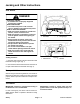
Jacking and Other Instructions Jack Vehicle DANGER POTENTIAL HAZARD • A vehicle that is not properly supported may become unstable. WHAT CAN HAPPEN • The vehicle may move or fall. Personal injury or damage to the machine may result. HOW TO AVOID THE HAZARD • Make sure vehicle is parked on a solid level surface, such as a concrete floor. • Make sure engine is off and key is removed from the ignition switch before getting off the vehicle.
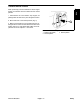
When performing routine maintenance and/or engine testing, the transaxle must be shifted into the neutral position. Safety Transaxle Neutral Position 2 1. Park machine on a level surface, stop engine, set parking brake and remove key from the ignition switch. 2. Move shift lever to the neutral position (Fig. 3). 1 3. Make sure transaxle is in the neutral position by rotating the driven clutch. The tires should not rotate.
Safety and Instruction Decals Numerous safety and instruction decals are affixed to your Workman. If any decal becomes illegible or damaged, install a new decal. Part numbers are listed in the Parts Catalog. Order replacement decals from your Authorized Toro Distributor.
Chapter 2 Product Records and Maintenance PRODUCT RECORDS . . . . . . . . . . . . . . . . . . . . . . . . . MAINTENANCE . . . . . . . . . . . . . . . . . . . . . . . . . . . . . . . EQUIVALENTS AND CONVERSIONS . . . . . . . . . . . Decimal and Millimeter Equivalents . . . . . . . . . . . . U.S. to Metric Conversions . . . . . . . . . . . . . . . . . . . TORQUE SPECIFICATIONS . . . . . . . . . . . . . . . . . . . . Fastener Identification . . . . . . . . . . . . . . . . . . . . . . .
Equivalents and Conversions 0.
Recommended fastener torque values are listed in the following tables. For critical applications, as determined by Toro, either the recommended torque or a torque that is unique to the application is clearly identified and specified in this Service Manual. These Torque Specifications for the installation and tightening of fasteners shall apply to all fasteners which do not have a specific requirement identified in this Service Manual.
Standard Torque for Dry, Zinc Plated and Steel Fasteners (Inch Series) Thread Size # 6 -- 32 UNC Grade 1, 5 & 8 with Thin Height Nuts SAE Grade 1 Bolts, Screws, Studs & Sems with Regular Height Nuts (SAE J995 Grade 2 or Stronger Nuts) in--lb in--lb N--cm 10 + 2 13 + 2 147 + 23 # 6 -- 40 UNF # 8 -- 32 UNC 13 + 2 25 + 5 282 + 30 # 8 -- 36 UNF # 10 -- 24 UNC 18 + 2 30 + 5 339 + 56 # 10 -- 32 UNF SAE Grade 5 Bolts, Screws, Studs & Sems with Regular Height Nuts (SAE J995 Grade 2 or Stronger N
Standard Torque for Dry, Zinc Plated and Steel Fasteners (Metric Fasteners) Class 8.8 Bolts, Screws and Studs with Regular Height Nuts (Class 8 or Stronger Nuts) Class 10.9 Bolts, Screws and Studs with Regular Height Nuts (Class 10 or Stronger Nuts) M5 X 0.8 57 + 5 in--lb 640 + 60 N--cm 78 + 7 in--lb 885 + 80 N--cm M6 X 1.0 96 + 9 in--lb 1018 + 100 N--cm 133 + 13 in--lb 1500 + 150 N--cm M8 X 1.25 19 + 2 ft--lb 26 + 3 N--m 27 + 2 ft--lb 36 + 3 N--m M10 X 1.
Other Torque Specifications SAE Grade 8 Steel Set Screws Wheel Bolts and Lug Nuts Thread Size Recommended Torque Thread Size Square Head Hex Socket 1/4 -- 20 UNC 140 + 20 in--lb 73 + 12 in--lb 5/16 -- 18 UNC 215 + 35 in--lb 145 + 20 in--lb 3/8 -- 16 UNC 35 + 10 ft--lb 18 + 3 ft--lb 1/2 -- 13 UNC 75 + 15 ft--lb 50 + 10 ft--lb Recommended Torque** 7/16 -- 20 UNF Grade 5 65 + 10 ft--lb 88 + 14 N--m 1/2 -- 20 UNF Grade 5 80 + 10 ft--lb 108 + 14 N--m M12 X 1.25 Class 8.
Chapter 3 Briggs & Stratton Gasoline Engine Table of Contents Workman MDX Page 3 -- 1 Briggs & Stratton Gasoline Engine GENERAL INFORMATION . . . . . . . . . . . . . . . . . . . . . 2 Operator’s Manual . . . . . . . . . . . . . . . . . . . . . . . . . . 2 SPECIFICATIONS . . . . . . . . . . . . . . . . . . . . . . . . . . . . . 3 ADJUSTMENTS . . . . . . . . . . . . . . . . . . . . . . . . . . . . . . 4 Adjust Throttle Cable . . . . . . . . . . . . . . . . . . . . . . . . 4 SERVICE AND REPAIRS . . . . .
General Information This Chapter gives information about specifications, maintenance, troubleshooting, testing and repair of the V--twin cylinder, gasoline engine used in the Workman MDX. gines. The use of some specialized test equipment is explained. However, the cost of the test equipment and the specialized nature of some repairs may dictate that the work be done at an engine repair facility. Most repairs and adjustments require tools which are commonly available in many service shops.
Specifications Item Description Make / Designation Briggs and Stratton, 4--cycle, V--Twin Cylinder, OHV, Air Cooled, Gasoline Engine -- Model 303440 Bore x Stroke 2.68” x 2.60” (68 mm x 66 mm) 29.3 in3 (480 cc) Total Displacement Mechanical Governor Carburetor Float Feed, Single Barrel Fuel Pump Pulsating Crankcase Vacuum Fuel Unleaded, regular grade gasoline Fuel Tank Capacity 7.0 U.S. gal (26.
Adjustments Adjust Throttle Cable NOTE: The Workman MDX is equipped with an engine governor. Refer to the Briggs & Stratton Repair Manual at the end of this chapter for governor information on these machines. 2 Depressing the accelerator pedal rotates the engine governor bellcrank which tensions the main governor spring to increase engine speed. Releasing the accelerator pedal decreases governor spring tension to reduce engine speed. 1.
Service and Repairs Cooling System To ensure proper engine cooling, make sure the grass screen, cooling fins and other external surfaces of the engine are kept clean at all times. NOTE: Perform this maintenance procedure at the interval specified in the Operator’s Manual. 1 IMPORTANT: The engine that powers the Workman MDX is air--cooled. Operating the engine with dirty or plugged cooling fins or a plugged or dirty blower housing will result in engine overheating and damage. 1.
Air Cleaner 5 4 6 7 8 1 60 to 65 in--lb (6.8 to 7.3 N--m) 9 3 10 2 11 12 19 13 17 12 14 15 18 16 17 RIGHT FRONT Figure 5 1. 2. 3. 4. 5. 6. Air cleaner assembly Bolt Compression spring Mounting band Nut Flange nut (2 used) Briggs & Stratton Gasoline Engine 7. 8. 9. 10. 11. 12. Cap screw (2 used) Air cleaner bracket Flange head screw (4 used) Carburetor gasket (2 used) Carburetor adapter Hose clamp Page 3 -- 6 13. 14. 15. 16. 17. 18.
Removal (Fig. 5) 2 1. Make sure machine is parked on a level surface with the engine OFF. 2. Raise cargo box and support with prop rod. 3 3. Thoroughly clean junction of intake hose and carburetor adapter on engine and air cleaner assembly. 4. Remove air cleaner components as needed using Figure 5 as a guide. Discard any removed gaskets and clean gasket mating surfaces. 4 1 Installation (Fig. 5) Figure 6 1. Air cleaner 2. Carburetor adapter 3. Breather hose 4. Intake hose 1.
Exhaust System RIGHT FRONT 9 4 10 1 2 7 6 5 4 3 8 Figure 7 1. 2. 3. 4. Muffler Swing arm Cap screw (2 used) Lock washer (6 used) Briggs & Stratton Gasoline Engine 5. Exhaust coupler 6. Coupler spring (4 used) 7. Exhaust manifold Page 3 -- 8 8. Engine tray 9. Engine 10.
Removal (Fig. 7) Installation (Fig. 7) 1. Park machine on a level surface, stop the engine, engage parking brake and remove the key from the ignition switch. NOTE: Mount all exhaust components loosely before tightening to ensure a proper fit of exhaust system. CAUTION The muffler and exhaust pipe may be hot. To avoid possible burns, allow engine and exhaust system to cool before working on the muffler. 3. Remove four (4) coupler springs securing the exhaust coupler to the muffler and exhaust manifold.
Fuel Tank RIGHT FRONT 1 15 16 11 10 2 3 9 8 7 12 5 6 13 4 14 13 1. 2. 3. 4. 5. 6. Seat Fuel gauge Bushing Gas cap Fuel tank Bushing Briggs & Stratton Gasoline Engine 7. 8. 9. 10. 11. Figure 8 Stand pipe Hose clamp Fuel hose (to fuel filter) Fuel line conduit Seat base Page 3 -- 10 12. 13. 14. 15. 16.
Fuel Tank Removal (Fig. 10) 4 CAUTION 2 Read safety precautions for handling gasoline before working on the fuel system (see Safety Instructions in Chapter 1 -- Safety). 1. Remove seat base from the frame (see Seat Base Removal in the Service and Repairs section of Chapter 7 -- Chassis). 5 1 3 2. Use fuel transfer pump to remove gas from fuel tank. 4. Release tank strap that secures fuel tank to frame. Do not remove strap from floor plate and frame cross member. Lift tank from frame. 1.
Oil Filter Assembly 1 1 2 40 to 50 in--lb (4.6 to 5.6 N--m) 40 to 50 in--lb (4.6 to 5.6 N--m) 3 4 3 4 5 12 6 11 8 7 10 8 9 7 RIGHT FRONT Figure 11 1. 2. 3. 4. Hose Elbow fitting Hose Fitting Briggs & Stratton Gasoline Engine 5. 6. 7. 8. Oil pressure switch Elbow fitting Cap screw (4 used) Flange nut (4 used) Page 3 -- 12 9. 10. 11. 12.
Removal (Fig. 11) Installation (Fig. 11) 1. Park machine on a level surface, stop the engine, engage parking brake and remove the key from the ignition switch. 1. Install removed oil filter adapter components using Figure 11 as a guide. Torque fittings (items 2, 4 and 6) from 40 to 50 in--lb (4.6 to 5.6 N--m). 2. Raise cargo box and support with prop rod. 2. Check and adjust engine oil level. 3.
Engine 5 4 6 41 40 RIGHT 30 FRONT 3 65 to 85 ft--lb (88 to 115 N--m) 39 8 33 8 9 22 38 31 28 10 13 1 37 42 Loctite #242 1 36 1 43 2 17 25 27 19 11 29 20 14 12 24 15 16 18 29 35 7 Loctite #242 23 34 21 26 44 25 to 30 ft--lb (34 to 40 N--m) 32 Figure 12 1. 2. 3. 4. 5. 6. 7. 8. 9. 10. 11. 12. 13. 14. 15.
Engine Removal (Fig. 12) 1. Park machine on a level surface, stop engine, engage parking brake and remove key from the ignition switch. 2. Disconnect negative (black) cable from the battery. Then, disconnect positive (red) cable from the battery. 3 3. Remove cargo box to gain access to the engine (see Cargo Box and Tailgate Removal in the Service and Repairs section of Chapter 7 -- Chassis). 4. Depending on needed engine repairs, it may be easier to drain engine oil from engine before engine removal.
11. Disconnect electrical connections from the following engine components: 6 A. Disconnect ground cable to engine at starter/ generator terminal A1 (Fig. 15). B. Disconnect engine harness connector from the main harness. 1 12.Remove four (4) flange nuts and cap screws securing the engine to the engine tray. 2 5 4 3 CAUTION One person should operate the hoist while the other person guides the engine out of the frame. 13.Remove engine from the engine tray. A.
10.Connect the following components (Fig. 13): A. Choke and throttle cables to the carburetor and cable bracket. 12.Connect positive (red) cable to the battery. Then, connect negative (black) cable to the battery. 13.Make sure engine oil level is correct. Briggs & Stratton Gasoline Engine B. Air intake hose to the air cleaner intake and machine frame. 11. Install cargo box to the frame (see Cargo Box and Tailgate Installation in the Service and Repairs section of Chapter 7 -- Chassis).
This page is intentionally blank.
Chapter 4 Single Cylinder Gasoline Engine Table of Contents Workman MD Page 4 -- 1 Single Cylinder Gasoline Engine GENERAL INFORMATION . . . . . . . . . . . . . . . . . . . . . 2 Operator’s Manual . . . . . . . . . . . . . . . . . . . . . . . . . . 2 SPECIFICATIONS . . . . . . . . . . . . . . . . . . . . . . . . . . . . . 3 ADJUSTMENTS . . . . . . . . . . . . . . . . . . . . . . . . . . . . . . 4 Adjust Throttle Cable . . . . . . . . . . . . . . . . . . . . . . . . 4 SERVICE AND REPAIRS . . . . . . . .
General Information This Chapter gives information about specifications, maintenance, troubleshooting, testing and repair of the single cylinder gasoline engine used in the Workman MD. Workman MD vehicles with serial numbers below 311000000 have an engine that is identified as a Kohler Command Pro CS engine. Workman MD vehicles with serial numbers above 311000000 have an engine that is identified as a Yamaha MZ360 engine. From a service standpoint, these engines are essentially the same.
Specifications Item Description Make / Designation 4--cycle, Single Cylinder, OHV, Air Cooled, Gasoline Engine Bore x Stroke 3.35 in x 2.48 in (85 mm x 63 mm) 21.8 in3 (357 cc) Total Displacement Governor Transaxle, Ground Speed Governing Carburetor Float Feed, Single Barrel Fuel Pump Pulsating Crankcase Vacuum Fuel Unleaded regular grade gasoline Fuel Tank Capacity 7.0 U.S. gal (26.5 l) Lubrication System Splash Lubrication 1.2 U.S. qt (1.
Adjustments Adjust Throttle Cable Releasing the accelerator pedal should allow the throttle cable to close the carburetor throttle control lever so that the lever touches the adjustment screw. The adjustment screw keeps the throttle valve inside the carburetor open slightly to prevent the valve from binding. 1 1. Park machine on a level surface, stop engine, engage parking brake and remove key from the ignition switch. 4 2. Lift cargo box and prop with rod to gain access to the engine and transaxle.
Service and Repairs Cooling System To ensure proper engine cooling, make sure the grass screen, cooling fins and other external surfaces of the engine are kept clean at all times. 1 NOTE: Perform this maintenance procedure at the interval specified in the Operator’s Manual. IMPORTANT: The engine that powers the Workman MD is air--cooled. Operating the engine with dirty or plugged cooling fins or a plugged or dirty blower housing will result in engine overheating and damage. 1.
Exhaust System RIGHT 12 3 4 FRONT 5 2 1 6 7 8 9 10 11 Figure 4 1. 2. 3. 4. Engine Coupler spring (4 used) Exhaust manifold Muffler Single Cylinder Gasoline Engine 5. 6. 7. 8. Exhaust coupler Starter/generator Drive clutch Engine tray Page 4 -- 6 9. 10. 11. 12.
Removal (Fig. 4) 3 1. Park machine on a level surface, stop the engine, engage parking brake and remove the key from the ignition switch. 1 2. Raise cargo box and support with prop rod. 2 3 CAUTION The muffler and exhaust pipe may be hot. To avoid possible burns, allow engine and exhaust system to cool before working on the muffler. 3. Remove four (4) springs securing the exhaust coupler to the muffler and exhaust manifold (Fig. 5). Figure 5 1. Exhaust manifold 2. Exhaust coupler 3. Spring 4.
Fuel Tank RIGHT FRONT 1 15 16 11 10 2 3 9 8 7 5 6 12 13 4 14 13 1. 2. 3. 4. 5. 6. Seat Fuel gauge Bushing Gas cap Fuel tank Bushing Single Cylinder Gasoline Engine 7. 8. 9. 10. 11. Figure 6 Stand pipe Hose clamp Fuel hose (to fuel filter) Fuel line conduit Seat base Page 4 -- 8 12. 13. 14. 15. 16.
Fuel Tank Removal (Fig. 6) CAUTION 4 2 Read safety precautions for handling gasoline before working on the fuel system (see Safety Instructions in Chapter 1 -- Safety). 1. Remove seat base from the frame (see Seat Base Removal in the Service and Repairs section of Chapter 7 -- Chassis). 5 1 3 2. Use fuel transfer pump to remove gas from fuel tank. 3. Loosen hose clamp and disconnect fuel hose from the fuel tank stand pipe. 4. Release tank web strapping from fuel tank.
Engine 37 48 36 35 RIGHT 52 62 3 42 57 4 40 5 FRONT 18 Loctite #242 20 17 65 to 85 ft--lb (88 to 115 N--m) 16 11 8 51 50 49 24 1 43 29 30 45 13 25 60 32 14 58 59 24 19 53 52 25 to 30 ft--lb (34 to 40 N--m) 9 12 46 38 15 20 22 27 2 10 26 54 39 55 7 21 23 31 Loctite #242 61 28 42 47 40 56 27 41 Loctite #242 33 44 24 34 6 Figure 9 1. 2. 3. 4. 5. 6. 7. 8. 9. 10. 11. 12. 13. 14. 15. 16. 17. 18. 19. 20. 21.
Engine Removal (Fig. 9) 1. Park machine on a level surface, stop engine, engage parking brake and remove key from the ignition switch. 2. Disconnect ground (black) cable from the battery. Then, disconnect positive (red) cable from the battery. 3. Remove cargo box to gain access to the engine (see Cargo Box and Tailgate Removal in the Service and Repairs section of Chapter 7 -- Chassis). IMPORTANT: Make sure all hoses and engine openings are plugged after disconnecting.
Engine Installation (Fig. 9) 1. Install all removed engine parts and attachments to the engine. 6. Install starter belt to the engine and starter/generator pulleys. Tension the belt by rotating the starter/generator away from the engine. Tighten fasteners to secure starter/generator. 7. Install drive belt to drive clutch. CAUTION One person should operate the hoist while a second person guides the engine into the frame. 2. Install engine to the frame. A.
Chapter 5 Drive Train Table of Contents GENERAL INFORMATION . . . . . . . . . . . . . . . . . . . . . 1 Operator’s Manual . . . . . . . . . . . . . . . . . . . . . . . . . . 1 SPECIFICATIONS . . . . . . . . . . . . . . . . . . . . . . . . . . . . . 2 DRIVE TRAIN OPERATION . . . . . . . . . . . . . . . . . . . . 3 Clutch System Operation . . . . . . . . . . . . . . . . . . . . . 3 Drive Clutch Operation . . . . . . . . . . . . . . . . . . . . . . . 4 Driven Clutch Operation . . . . . . . . . . . . . . . . .
Specifications Item Description Transaxle Transaxle Fluid Capacity Transaxle Fluid 1.5 quarts (1.
Drive Train Operation Clutch System Operation 1 3 A B 4 6 C 7 5 Drive Train 9 v 8 2 Figure 1 1. Drive clutch (engine mounted) 2. Driven clutch (transaxle mounted) 3. Moveable sheave (drive clutch) 4. Fixed sheave (drive clutch) 5. Moveable sheave (driven clutch) 6. Button Power is transferred from the engine to the transaxle by a variable clutch system that consists of two clutches connected by a drive belt. The drive clutch responds to engine speed, and is mounted to the engine drive shaft.
Drive Clutch Operation The operation of the drive clutch is affected by engine shaft speed. When the engine is off and not turning, the drive belt rests low within the drive clutch sheaves as the clutch sheaves are spaced apart. As the engine is started and increases in speed, the clutch weights move outward as they spin about the engine drive shaft. The outward movement of the weights against the spider assembly forces the moveable sheave closer to the fixed sheave.
Driven Clutch Operation The operation of the driven clutch is affected by transaxle load. When the vehicle is stopped, the drive belt is held at the outer diameter of the driven clutch sheaves from the pressure of the spring pushing the moveable sheave against the fixed sheave and away from the fixed cam. 1 5 2 Once the drive belt starts rotating, the driven clutch also starts to rotate.
Special Tools Order special tools from your Toro Distributor. Drive Clutch Removal Tool (Serial Number Below 310000000) This tool is required to remove the drive clutch from the tapered drive shaft of the engine. It is placed in the threaded hole of the fixed clutch sheave after the clutch holding cap screw is removed. Toro Part Number: TOR4094 NOTE: Vehicles with a serial number below 310000000 are equipped with a Comet brand drive clutch.
Drive Clutch Removal Tool (Serial Number Above 310000000) This tool is required to remove the drive clutch from the tapered drive shaft of the engine. It is placed in the threaded hole of the fixed clutch sheave after the clutch holding cap screw is removed. Toro Part Number: TOR6013 NOTE: Vehicles with a serial number above 310000000 are equipped with a TEAM brand drive clutch. Figure 8.
This page is intentionally blank. Drive Train Page 5 -- 6.2 Rev.
Adjustments Adjust Ground Speed (Workman MD) Workman MD models are equipped with a transaxle governor. Adjust ground speed using the following procedure. 7. Adjust throttle cable (accelerator pedal to transaxle) at the cable bracket until the correct driven clutch RPM is obtained with the accelerator pedal fully to the floor (Fig. 8). 8. Install anti--tamper bracket to the cable bracket using a new anodized rivet (Toro P/N 99--7122) (Fig. 8).
Adjust Ground Speed (Workman MDX) Workman MDX models use an engine governor for speed control. Adjust ground speed using the following procedure. 2 3 1 WARNING Vehicles operating at ground speeds greater than the recommended speed will require further distances to fully stop. Do not adjust ground speed greater than specified. 1. Park machine on a level surface, stop engine, set parking brake and remove key from the ignition switch. Raise and support cargo box. 2.
Adjust Shift Cables 1. Park machine on a level surface, stop engine, set parking brake and remove key from the ignition switch. Raise and support cargo box. 2. Set the shift lever into the Neutral position. Rotate driven clutch to insure transmission is in neutral. 3 3. The transaxle select lever assembly should be in a level position and parallel to the cable mounting bracket. 2 4. While holding the cable below the lever, tighten the lock nut on one of the shift cables to allow 0.030” to 0.060” (0.
Service and Repairs Drive Clutch 13 1 3 2 Loctite #242 25 to 30 ft--lb (34 to 40 N--m) 8 14 4 v 11 5 6 7 RIGHT 9 FRONT 10 Loctite #242 12 Figure 12 1. 2. 3. 4. 5. Engine (V--twin shown) Starter/generator Starter/generator belt Starter/generator pulley Cap screw (4 used) 6. 7. 8. 9. 10. Lock washer (4 used) Engine starter pulley Spacer Drive clutch Washer 11. 12. 13. 14.
NOTE: The drive clutch on vehicles with serial numbers above 310000000 is different than the clutch used on earlier vehicles. The procedure to remove or install the drive clutch is the same regardless of machine serial number. Drive Clutch Removal (Fig. 13) 1. Park machine on a level surface, stop engine, set parking brake and remove key from the ignition switch. Raise and support cargo box. 2. Remove drive belt from the drive clutch. 3. Remove starter/generator V--belt from the engine pulley. 4.
Drive Clutch Service (Serial Number Below 310000000) 1 100 ft--lb (136 N--m) 11 75 to 100 in--lb (8.5 to 11.3 N--m) 4 5 2 3 12 10 8 6 7 9 v Figure 14 1. 2. 3. 4. Fixed sheave Spring Washer Spider assembly 5. 6. 7. 8. Cap screw (3 used) Plastic cap Cover Moveable sheave 9. 10. 11. 12. Roller kit (3 used) Cam weight (3 used) Lock nut (3 used) Pilot bolt (3 used) NOTE: Vehicles with a serial number below 310000000 are equipped with a Comet brand drive clutch. 3.
3. Use two 1/4--20 X 1” cap screws to secure the spider removal holding bar (see Special Tools) to drive clutch (Fig. 16). 4. Secure clutch with attached spider removal holding bar in a vise. Matchmark position of spider and moveable sheave for reassembly purposes. CAUTION Remove spider from fixed sheave slowly. The moveable sheave is under pressure from the spring. IMPORTANT: Use spider removal spanner to remove spider. Unequal pressure on the cam towers may damage them. Figure 15 2 5.
3. Assemble cam weights to moveable sheave as follows: A. Make sure the threads of the pilot bolts are clean and dry. Apply Loctite #271 (or equivalent) to the threads of each bolt. IMPORTANT: To maintain the balance of the clutch, all pilot bolts must be installed with their threads pointing in a clockwise direction (Fig. 19). B. Immediately install new lock nuts on the pilot bolts. Tighten nuts until they just touch the sheave casting. Never reuse lock nuts. 4.
Drive Train This page is intentionally blank. Workman MD/MDX Page 5 -- 13.2 Rev.
Drive Clutch Service (Serial Number Above 310000000) 132 to 168 in--lb (15.0 to 18.9 N--m) 1 8 6 3 9 2 7 5 10 11 190 to 220 ft--lb (258 to 298 N--m) 132 to 168 in--lb (8.5 to 11.3 N--m) 4 v Figure19.1 1. 2. 3. 4. Fixed sheave Limiter shim Shim Spider 5. 6. 7. 8. Cap screw (3 used) Roller (6 used) Cover Moveable sheave NOTE: Vehicles with a serial number above 310000000 are equipped with a TEAM brand drive clutch. Drive Clutch Disassembly (Fig. 19.
Drive Clutch Inspection NOTE: If drive clutch wear or damage occurs, clutch replacement may be necessary. Refer to your parts catalog to identify individual drive clutch components that are available. 1. Inspect the tapered ends of the engine crankshaft and fixed sheave of drive clutch. If either is severely damaged, replace component as damage to the taper will allow loosening of the clutch during machine operation. 2 1 2. Check all of the rollers.
Driven Clutch NOTE: The driven clutch on vehicles with serial numbers above 310000000 is different than the clutch used on earlier vehicles. The procedure to remove or install the driven clutch is the same regardless of machine serial number. 3 4 2 Driven Clutch Removal (Fig. 20) 1. Park machine on a level surface, stop engine, set parking brake and remove key from the ignition switch. Raise and support cargo box. 2.
Driven Clutch Service (Serial Number Below 310000000) Ramp Button Replacement (Fig. 21) 1. Park vehicle on a level surface, stop engine, set parking brake and remove key from the ignition switch. Raise and support cargo box. 2. Remove drive belt from the driven clutch (see Service Drive Belt in Service and Repairs section of Engine Chapter). 3. Turn fixed and moveable sheaves in opposite directions so button is separated sufficiently enough from the ramp to allow removal. 4.
Driven Clutch Service (Serial Number Above 310000000) NOTE: Vehicles with a serial number above 310000000 are equipped with a TEAM brand driven clutch (Fig. 21.1). 2 3 1. Use a suitable press to compress the clutch spring enough to allow removal of the retaining ring (item 7). 4 2. Remove retaining ring. 6 7 3. Carefully, allow the spring to extend fully. 4. Remove outer spring retainer, spring and inner spring retainer from clutch. 5.
Drive Train This page is intentionally blank. Workman MD/MDX Page 5 -- 15.2 Rev.
Transaxle Antiseize Lubricant 9 7 39 to 47 ft--lb (53 to 63 N--m) 8 6 10 11 5 12 14 4 2 3 1 RIGHT v FRONT 13 20 15 14 17 19 16 18 Figure 22 1. 2. 3. 4. 5. 6. 7. Engine Washer (4 used) Cap screw (4 used) Drive belt Cap screw Stepped washer Driven clutch 8. 9. 10. 11. 12. 13. 14. Transaxle Lock nut Flat washer Shift cable (2 used) Flange nut (4 used) Engine tray Swing arm Removal (Fig. 22) 1.
6. On Workman MD, remove governor and cable brackets from the transaxle as follows (Fig. 23). 3 1 A. Scribe mark across governor bracket and governor shaft to help installation. Loosen both set screws securing the bracket to the shaft. 4 2 B. Remove both lock nuts securing the cable bracket to the transaxle case. Remove both brackets and cables as a complete assembly from the transaxle case and governor shaft. 7.
IMPORTANT: Take care to not damage the engine, fuel hoses, electrical harness or other parts while lowering the engine tray assembly. 13.Carefully move engine tray assembly toward the rear of the vehicle to clear mounts on swing arm. Then, lower engine tray enough to allow the transaxle and driven clutch to be removed from the rear of the vehicle. Support engine tray in this position to prevent it from shifting or falling. 14.
Workman MD/MDX Page 5 -- 19 Drive Train This page is intentionally blank.
Transaxle Service 56 69 55 52 52 57 75 25 to 31 ft--lb (34 to 42 N--m) 55 50 74 72 76 73 35 29 67 53 65 70 3 4 5 13 70 9 11 10 6 58 24 12 to 16 in--lb (1.4 to 1.
Figure 26 (Continued) 1. 2. 3. 4. 5. 6. 7. 8. 9. 10. 11. 12. 13. 14. 15. 16. 17. 18. 19. 20. 21. 22. 23. 24. 25. 26.
2 1 Figure 28 1. Bolt (steel ball, spring & gasket) 2. Selector shaft C. Remove bolt near the selector shaft. Remove spring and steel ball. Replace gasket if damaged. 2 1 Figure 29 1. Input shaft 2. Oil seal D. Wrap vinyl tape around the splined portion of the input shaft. This should protect the oil seal from being damaged.
1 3 2 Figure 30 1. Flange bolts (3 used) 2. Axle bracket 3. Axle case Drive Train E. Remove three (3) flange bolts securing the axle bracket and axle case to each case. Separate bracket from each axle case. 2 1 Figure 31 1. Flange bolt (10 used) 2. Flange nut F. With the input shaft side down, loosen and remove flange bolts and nuts securing the case (RH) and case (LH) together.
1 2 Figure 32 1. Case (RH) 2. Governor boss G. Hold the case (RH) and lift up while lightly tapping the governor boss with a plastic hammer. IMPORTANT: Make sure to not hit the governor boss too hard when separating the cases, the boss may get damaged. Do not pry open the two cases with a screw driver, damage may result to the sealing surfaces. 2. Remove input shaft, center shaft and differential assemblies. 2 1 Figure 33 1. Gasket 2. Pipe knock A. Remove gasket and pipe knocks.
4 1 3 2 Figure 34 1. Counter shaft 2. Spacer (2 used) 3. Needle bearing 4. Gear 34 Drive Train B. Pull out counter shaft. Remove spacer, needle bearing, gear 34 and spacer. 3 2 2 1 4 Figure 35 1. Counter shaft 2. Spacer (2 used) 3. Needle bearing 4. Gear 34 C. Replace counter shaft if it has abnormal wear, cracks or damage. E. Replace needle bearing if needles are bent, do not rotate freely or do not remain in the bearing cage. D. Replace spacer if either one is cracked or bent. F.
4 1 3 2 Figure 36 1. Differential assembly 2. Input shaft assembly 3. Center shaft assembly 4. Shift shaft G. Lift up differential assembly, center shaft assembly and input shaft assembly at the same time. First, remove input shaft assembly. Then, remove center shaft assembly with the shift shaft and differential assembly. IMPORTANT: Make sure not to damage the oil seal when removing the input shaft.
2 4 3 1 Figure 38 1. Snap ring 2. Axle case 3. Axle shaft 4. Ball bearing C. Ball bearing roller balls must be free of deformation and scoring. Ball bearing must spin freely and have minimum axial play. Replace ball bearing as necessary. IMPORTANT: Do not reuse snap ring. Discard and replace ring with new one. B. Remove snap ring from the axle case. Remove axle shaft from case. IMPORTANT: When replacing ball bearings, both ball bearings must be replaced as a set. Drive Train 4.
1 2 Figure 40 1. Ball bearing 2. Input shaft B. Remove ball bearing from the input shaft with a bearing puller. IMPORTANT: Do not reuse ball bearings that have been removed. 1 2 Figure 41 1. Governor plate assembly 2. Governor base IMPORTANT: Make sure to not damage the screw heads when removing screws. Each screw is secured with an adhesive. Drive Train C. On Workman MD, remove two (2) screws and lock pin securing the governor plate assembly to the governor base.
1 4 2 3 5 6 Figure 42 1. Input shaft 2. Ball bearing 3. Governor plate (weight) (WM MD) 4. Governor sleeve (Workman MD) 5. Lock pin (Workman MD) 6. Screw (2 used) (Workman MD) D. Replace input shaft if worn or damaged. Gear teeth that are cracked, broken, chipped or missing are not acceptable. F. On Workman MD, replace governor plate if cracked, bent or any weight is missing. Weights must swing freely. E. Ball bearing roller balls must be free of deformation and scoring.
8 5 3 8 2 7 4 1. 2. 3. 4. 5. 9 1 6 Gear 55 Gear 47 Gear (small) Ball bearing Ball bearing Figure 44 6. 7. 8. 9. B. Remove gears, pin clutch, collars and spacer from the input shaft. C. Replace gears if worn or damaged. Cracked, broken, missing or chipped gear teeth are not acceptable. Drive Train Pin clutch Center shaft Collar (2 used) Spacer D. Replace center shaft if worn or damaged. Splines that are cracked, broken, chipped or missing are not acceptable. E.
6. Disassemble differential case assembly. 1 2 3 Figure 45 1. Bolt (6 used) 2. Gear 62 3. Differential case A. Remove six (6) bolts securing gear 62 to the differential case. 3 4 Drive Train 4 1 2 Figure 46 1. Spring pin 2. Differential case 3. Pinion shaft 4. Pinion gear NOTE: The spring pin can be punched out from the hole on the opposite side of gear 62. C. Remove pinion shaft and gears from the case. Separate gears from shaft. B. Remove spring pin from the differential case.
5 4 3 6 2 8 1 7 Figure 47 1. 2. 3. 4. Side gear (2 used) Pinion gear (2 used) Gear 34 Ball bearing 5. 6. 7. 8. Differential case Pinion shaft Spring pin Bolt (6 used) D. Replace gears if worn or damaged. Cracked, broken, missing or chipped gear teeth are not acceptable. F. Replace case if machined areas where the side and pinion gears mesh are scored or if the pinion shaft fits loosely in its bore. E. Ball bearing roller balls must be free of deformation and scoring.
7. On Workman MD, disassemble governor fork and shaft. 3 4 2 1 Figure 48 3. Governor fork 4. Case (RH) A. Remove both screws and washers securing the stopper and governor fork to the case (RH). Remove stopper and fork from the case. IMPORTANT: Make sure to not damage the screw heads when removing screws. Each screw is secured with an adhesive. Drive Train 1. Screw (2 used) 2. Stopper 1 3 2 Figure 49 1. Governor shaft 2. Boss 3.
2 5 6 4 1 3 Figure 50 1. Ball bearing 2. Case (RH) 3. Governor shaft 4. Governor fork 5. Stopper 6. Screw (2 used) D. Remove ball bearing from the case. Ball bearing roller balls must be free of deformation and scoring. Ball bearing must spin freely and have minimum axial play. Replace ball bearing as necessary. Drive Train E. Replace governor shaft if cracked, bent or excessively worn. F. Replace governor fork or stopper if bent or deformed.
Transaxle Assembly 1. Assemble input shaft assembly. 4 1 3 12 to 16 in--lb (1.4 to 1.8 N--m) 2 Figure 51 1. Governor plate 2. Governor base 3. Screw 4. Governor sleeve A. On Workman MD, secure governor plate unit to the governor base with two (2) screws and lock pin. Torque fasteners from 12 to 16 in--lb (1.4 to 1.8 N--m). Drive Train IMPORTANT: To prevent the screws that secure the governor plate to the governor from loosening, apply Loctite #242 (or equivalent) to the screw threads.
1 2 Figure 53 1. Governor sleeve 2. Input shaft C. On Workman MD, apply molybdenum disulfide grease to the inside of the governor sleeve. Slide sleeve onto the input shaft. Make sure to engage sleeve slot with lock pin. 1 2 Figure 54 1. Pivot point 2. Governor plate D. On Workman MD, make sure to apply molybdenum disulfide grease to the pivot points of the weights on the governor plate unit.
2. Assemble the center shaft assembly. 3 4 7 1 8 6 9 5 5 2 136.8 to 137.1 mm Figure 55 6. 7. 8. 9. Pin clutch Center shaft Gear 47 Gear 55 Collar NOTE: Before assembling, apply molybdenum disulfide grease to the inside of gears 47 and 55. Gear (small) Bearing Bearing Spacer A. Slide pin clutch onto the centershaft. Install gears 47 and 55 onto shaft noting correct orientation of gears. Slide collars, small gear and spacer onto the center shaft. 1 2 Figure 56 1. Ball bearing 2. Ball bearing B.
Figure 57 D. The center shaft should appear as above when assembled. 3. Assemble differential assembly. 5 6 2 1 4 8 9 3 3 7 1 123.3 to 124.0 mm Figure 58 1. 2. 3. 4. 5. Pinion gear (greased surface) Pinion shaft Side gear (greased surface) Differential case Gear 62 6. 7. 8. 9. Bolt Spring pin Ball bearing Ball bearing A. Apply molybdenum disulfide grease to the inside of both pinion gears where they contact the pinion shaft.
1 4 3 2 Figure 59 1. Side gear 2. Pinion gear 3. Pinion shaft 4. Differential case B. Install side gear, both pinion gears and pinion shaft into the differential case. 3 1 Drive Train 2 Figure 60 1. Spring pin 2. Differential case 3. Pinion shaft C. Align pinion shaft hole and install new spring pin through the differential case and pinion shaft.
3 1 2 4 Figure 61 1. Side gear 2. Pinion gear 3. Gear 62 4. Differential case D. Install remaining side gear to the pinion gears. E. Secure gear 62 to the differential case with six (6) bolts. Torque bolts in a crossing pattern from 40 to 45 ft--lb (54 to 61 N--m). 40 to 45 ft--lb (54 to 61 N--m) Figure 62 IMPORTANT: The length from the outer most side of each ball bearing must be from 123.3 to 124.0 mm (Fig. 58). G. The differential assembly should appear as above when assembled. F.
4. On Workman MD, assemble governor fork. 2 1 Figure 63 1. Ball bearing 2. RH case (bearing bore) A. Install ball bearing into the bore of the case (RH). Drive Train 1 2 Figure 64 1. Governor shaft 2. Boss IMPORTANT: Make sure to not damage the oil seal when installing the governor shaft into the governor boss. Workman MD/MDX B. Lubricate governor shaft with molybdenum disulfide grease before installing. C. Install governor shaft into the boss.
4 3 2 1 Figure 65 1. Screw (2 used) 2. Stopper 3. Governor fork 4. Case (RH) D. Secure stopper and governor fork to the governor shaft with both screws. IMPORTANT: To prevent the screws that secure the governor fork and stopper to the governor shaft from loosening, apply Loctite #242 (or equivalent) to the screw threads. 12 to 16 in--lbs (1.4 to 1.8 N--m) 3 0.020” (0.5 mm) 2 1 Figure 66 1. Governor fork 2. Governor shaft (greased surface) E.
5. Install axle case to case (RH and LH). 2 3 1 Figure 67 1. Axle shaft 2. Snap ring 3. Ball bearing A. Insert axle shaft with snap rings, collar and ball bearings into the axle case. Install snap ring to the axle case. IMPORTANT: Do not reuse snap ring. Replace snap ring with new one. 3 1 Drive Train 25 to 31 ft--lb (34 to 42 N--m) 2 Figure 68 1. Axle case 2. Case 3. Flange bolt IMPORTANT: Make sure to install the axle case to the proper side of the case.
6. Install input shaft, center shaft and differential assemblies to the case. 2 1 Figure 69 1. Shift shaft 2. Clutch groove A. Insert fork of the shift shaft to the clutch groove of the center shaft assembly. 3 1 2 4 Figure 70 1. Center shaft assembly 2. Shift shaft 3. Input shaft 4. Differential assembly B. Replace oil seals for the input and selector shafts on the case (LH) if cracked, nicked or distorted such that they would not hold a proper seal.
1 2 Figure 71 1. Fork (selector shaft) 2. Pin (shift shaft) D. Make sure the selector shaft fork is contacting the pin on the shift shaft. Drive Train 1 2 Figure 72 1. Spacer 2. Boss (counter shaft) E. Place spacer on the counter shaft boss of the case (LH) so the oil groove faces up.
2 3 1 Figure 73 1. Gear 34 2. Counter shaft 3. Spacer F. Apply molybdenum disulfide grease to the inside of gear 34 and the contact surface between the case and the counter shaft. G. Place gear 34 onto the spacer. Make sure not to drop the spacer. Insert needle bearing into gear. Insert counter shaft with remaining spacer through the needle bearing, gear 34 and into the spacer and case. 7. Assemble case (LH and RH). 1 2 Figure 74 1. Case (sealing surface) 2. Pipe knock A.
1 2 15 to 18 ft--lb (21 to 25 N--m) Figure 75 1. Governor shaft (Workman MD) 2. Bolt C. Install case (RH) so each shaft fits properly into the case. NOTE: When installing case (RH) to the case (LH) on Workman MD, hold governor shaft so the ball bearing will not drop off. Keep the gasket sealing surfaces of the cases as horizontal to each other as possible. If the sealing surfaces do not join to each other, tap the case lightly with a plastic hammer. Drive Train D.
12 to 15 ft--lb (16 to 20 N--m) 2 1 Figure 77 1. Cable bracket 2. Bolt (steel ball, spring & gasket) F. Install cable bracket to the transaxle. G. Install steel ball, spring, gasket and bolt. Torque bolt from 12 to 15 ft--lb (16 to 20 N--m). Drive Train H. Fill transaxle with 1.5 quarts (1.4 liters) of new 10W--30 motor oil.
Chapter 6 Electrical System Table of Contents SERVICE AND REPAIRS . . . . . . . . . . . . . . . . . . . . . Starter/Generator . . . . . . . . . . . . . . . . . . . . . . . . . . Removal . . . . . . . . . . . . . . . . . . . . . . . . . . . . . . . . . Installation . . . . . . . . . . . . . . . . . . . . . . . . . . . . . . . Starter/Generator Service . . . . . . . . . . . . . . . . . . . Brush and Brush Spring Service . . . . . . . . . . . . Armature and Field Coil Service . . . . . . . . . . . .
General Information Operator’s Manual The Operator’s Manual provides information regarding the operation, general maintenance and maintenance intervals for your Workman vehicle. Refer to the Operator’s Manual for additional information when servicing the machine. Electrical Schematics The electrical schematics and other electrical drawings for the Workman MD and MDX are located in Chapter 8 -- Electrical Diagrams.
Special Tools Order special tools from your Toro Distributor. Some tools may also be available from a local supplier. Multimeter The meter can test electrical components and circuits for current, resistance or voltage. NOTE: Toro recommends the use of a DIGITAL Volt-Ohm--Amp multimeter when testing electrical circuits. The high impedance (internal resistance) of a digital meter in the voltage mode will make sure that excess current is not allowed through the meter.
Battery Hydrometer Use the Battery Hydrometer when measuring specific gravity of battery electrolyte. Obtain this tool locally.
Troubleshooting For effective troubleshooting and repairs, you must have a good understanding of the electrical circuits and components used on this vehicle (see Wiring Schematics in Chapter 8 -- Electrical Diagrams). CAUTION Remove all jewelry, especially rings and watches, before doing any electrical troubleshooting or testing. Disconnect the battery cables unless the test requires battery voltage.
General Run Problems Problem Possible Causes Battery does not charge. Wiring to the charging circuit components is loose, corroded or damaged (see Wiring Schematics in Chapter 8 -- Electrical Diagrams). Voltage regulator and/or starter/generator is faulty. Battery is faulty. Engine stops during operation. Wiring to the run circuit components became broken or disconnected (see Wiring Schematics in Chapter 8 -Electrical Diagrams). RPM shutdown module is faulty (Workman MDX).
Electrical System Quick Checks Battery Test Use a multimeter to measure the voltage between the battery terminals. Voltage Measured Battery Charge Level 12.68 V (or higher) Fully charged (100%) Set the multimeter to the DC volts setting. The battery should be at a temperature of 60o to 100o F. The ignition key should be off and all accessories turned off. Connect the positive (+) meter lead to the positive battery post and the negative (--) meter lead the the negative battery post. 12.
Component Testing For accurate resistance and/or continuity checks, electrically disconnect the component being tested from the circuit (e.g. unplug the ignition switch connector before doing a continuity check on the switch). NOTE: See the Briggs and Stratton Repair Manual for 4 Cycle, V--Twin Cylinder, OHV Head Engines (Workman MDX) or the Kohler Service Manual for Command Pro CS Series Engines (Workman MD) for additional component testing information.
Hour Meter Testing IMPORTANT: Make sure to observe polarity on the hour meter terminals when testing. Damage to the meter may result from an improper connection. QUARTZ 1. Unplug wire harness connector from hour meter. 00000 RUNNING: INDICATOR WINDOW 1 -10 HOURS 2. Connect positive (+) terminal of a 12 VDC source to the positive terminal of the hour meter. 1/10 WHEEL: WHITE W/BLACK NUMBERS HOUR WHEELS: BLACK W/WHITE NUMBERS 3.
Start/Run Solenoid The start/run solenoid provides a current path between starter/generator and the vehicle electrical circuits. This solenoid is energized when the ignition switch is ON and the accelerator pedal is depressed. The solenoid is attached beneath the cargo box to a bracket on the right hand side of the rear frame (Fig. 8). 8 7 1 6 Testing NOTE: Prior to taking small resistance readings with a digital multimeter, short the meter test leads together.
Fuse Block The fuse block is located beneath the dash panel. Fuses can be removed to check continuity. The test meter should read less than 1 ohm. 2 1 3 Fuses protect circuits as follows (Fig. 10): 4 1. The extreme left fuse protects the optional accessory circuit (if equipped). 2. The middle left 10 ampere fuse protects the ignition system and horn circuits. 3. The middle right 10 ampere fuse protects the light circuit. 3. Lights fuse 4. Power point fuse Electrical System 4.
Accelerator Switch The accelerator switch is a four (4) terminal, two (2) circuit switch. The switch is attached to the pedal support (Fig. 11). 5 1 6 When the accelerator pedal is pushed, the switch allows current flow to the start/run solenoid, hour meter and engine oil indicator and also provides an open circuit to the engine ignition system to allow the magneto ignition to operate.
Starter/Generator & Voltage Regulator 1. Place machine shift lever in the NEUTRAL position. Apply parking brake. 7. Reconnect green wire connector from the regulator and test voltage regulator: 2. Raise cargo box and secure with prop rod. Gain access to electric components by removing the electrical cover. A. Set multimeter to VDC. Connect red (+) probe of the multimeter into the green wire connection. Connect black (--) probe of the multimeter to a known good ground. 3.
Starter/Generator Testing of starter/generator field and armature windings is difficult with the starter/generator still mounted in the Workman. Follow the procedures for Starter Generator & Voltage Regulator Component Testing prior to removing the starter generator for further testing and repairs. DF F1 Starter generator resistance tests are as follows: NOTE: Prior to taking small resistance readings with a digital multimeter, short the meter test leads together.
Diode Assembly The diode D1 (Fig. 17) is used to protect the ignition switch from voltage spikes that can occur when the starter solenoid is de--energized. The diode plugs into the wiring harness. 1 2 Testing The diode can be tested using a digital multimeter (diode test or ohms setting) and the table to the right. 3 Figure 17 1. Diode 2. Male terminal 3.
Oil Pressure Switch (Workman MDX) The oil pressure switch is located on the mounting adapter for the oil filter. It is a normally closed switch that opens with pressure. 4. If the light is still on, check for short circuiting in the indicating circuit (see Electrical Schematic in Chapter 8 -- Electrical Diagrams). Oil pressure switch testing 5. Refer to the Briggs and Stratton Repair Manual for 4 Cycle, V--Twin Cylinder, OHV Head Engines for additional testing information. 1.
Reverse Switch (Optional) The optional reverse switch is a four (4) terminal, two (2) circuit switch that is used to energize the audio alarm when the shift lever is in the reverse position. The normally open switch circuit is used while the normally closed switch circuit is not used. If equipped, this switch is attached to the shift bracket in the seat base (Fig. 21). Testing 1. Place machine shift lever in the NEUTRAL position.
Service and Repairs NOTE: For information on electrical engine components, see the Briggs and Stratton Vanguard Service and Repair Manual for 4--Cycle, V--Twin Cylinder, OHV Engines (Workman MDX) or the Kohler Service Manual for Command Pro CS Series Engines (Workman MD). Starter/Generator 1 6 5 2 3 4 14 13 9 v 8 10 15 to 25 ft--lb (21 to 33 N--m) 7 RIGHT FRONT 12 11 Figure 23 1. 2. 3. 4. 5. Engine Lock nut Woodruff key Starter/generator pulley Starter/generator belt Electrical System 6. 7.
Removal (Fig. 23) Installation (Fig. 23) 1. Park vehicle on a level surface, stop engine, set parking brake and remove key from the ignition switch. 1. If removed, install pulley to the starter/generator shaft: 2. Raise cargo box and secure with prop rod to gain access to the starter/generator. A. Position woodruff key to the shaft. Slide pulley onto the shaft with the larger diameter pulley hub installed toward starter/generator.
Starter/Generator Service 8 16 21 7 22 24 23 19 20 WIRING DIAGRAM MOTOR 17 18 F2 13 FIELD(STATOR) F1 ARMATURE (ROTOR) A2 DF REG. 12 A1 9 14 1 6 3 15 to 25 ft--lb (20 to 34 N--m) 15 2 10 11 4 96 to 104 in--lb (10.8 to 11.8 N--m) 35 to 43 in--lb (4.0 to 4.9 N--m) 5 21 8 23 24 1 2 16 17 14 7 9 18 5 10 11 3 4 6 12 15 Figure 24 1. 2. 3. 4. 5. 6. 7. 8.
Brush and Brush Spring Service (Fig. 24) IMPORTANT: When removing or installing the commutator end cover, make sure brushes do not contact the commutator. Damage to the brushes may result. 10.Slide brushes into holders. Secure brushes by positioning brush springs into the notch at the end of the brushes (Fig. 27). 11. Install brush covers to the commutator end cover. 1. Remove brush covers from the commutator end cover.
6. Clean and inspect commutator. Armature and Field Coil Service (Fig. 24) A. Remove carbon dust, dirt and oil from the commutator. IMPORTANT: When removing the commutator end cover, make sure brushes do not contact the commutator. Damage to the brushes may result. B. Lightly remove slight roughness, burning or glazing of the commutator with 400 grit (or finer) sandpaper. Clean commutator after sanding. 1. Remove brush covers from the commutator end cover.
I. Position commutator end cover carefully to the commutator and yoke. Align end cover to the yoke with the locating pin. IMPORTANT: Do not remove field coils unless they are to be replaced. 10.To remove field coils (Fig. 29): J. Secure both end covers to the yoke with both through bolts and flat washers. Torque bolts from 96 to 104 in--lbs (10.8 to 11.8 N--m). A. Remove nuts from threaded terminal. Slide insulator and terminal out of yoke. B.
Rework Starter/Generator (Fig. 24) NOTE: Rework to the starter/generator must be performed by a properly trained technician using the correct tools and equipment for testing and reworking electrical motors and generators. It may be more economically feasible to replace the starter/generator than have it reworked. Detail Specification Minimum commutator diameter 1.575 inches (40 mm) Commutator concentricity to the shaft 0.0003 inch (0.008 mm) Commutator machining limit per cut 0.005 inch (0.
Battery Service WARNING POTENTIAL HAZARD: Either the battery terminals or metal tools could short against metal vehicle components. WHAT CAN HAPPEN: Sparks can cause the battery gasses to explode. Damaged cables could short against metal vehicle components and cause sparks. HOW TO AVOID THE HAZARD: When removing or installing the battery, do not allow the battery terminals to touch any metal parts of the vehicle.
Battery Inspection and Maintenance FILLER CAPS CAP TUBES WARNING CORRECT WATER LEVEL POTENTIAL HAZARD: Battery electrolyte contains sulfuric acid which is a deadly poison and it causes severe burns. WHAT CAN HAPPEN: If you carelessly drink electrolyte you could die or if it gets onto your skin you will be burned. HOW TO AVOID THE HAZARD: Do not drink electrolyte and avoid contact with skin, eyes or clothing. Wear safety glasses to shield your eyes and rubber gloves to protect your hands.
C. If the battery has been charged, apply a 150 amp load for 15 seconds to remove the surface charge. Use a battery load tester following the manufacturer’s instructions. Battery Testing 1. Conduct a hydrometer test of the battery electrolyte: IMPORTANT: Make sure the area around the cells is clean before opening the battery caps. D. Measure the temperature of the electrolyte in the center cell. A. Measure the specific gravity of each cell with a hydrometer.
Battery Charging To minimize possible damage to the battery and allow the battery to be fully charged, the slow charging method is presented here. This charging method can be accomplished with a constant current battery charger which is available in most shops. Follow the battery charger manufacturer’s instructions when using a battery charger. NOTE: Using specific gravity of the battery cells is the most accurate method of determining battery condition. 1.
Chapter 7 Chassis Table of Contents GENERAL INFORMATION . . . . . . . . . . . . . . . . . . . . . 1 Operator’s Manual . . . . . . . . . . . . . . . . . . . . . . . . . . 1 SPECIFICATIONS . . . . . . . . . . . . . . . . . . . . . . . . . . . . . 2 SPECIAL TOOLS . . . . . . . . . . . . . . . . . . . . . . . . . . . . . 2 TROUBLESHOOTING . . . . . . . . . . . . . . . . . . . . . . . . . 3 Suspension and Steering . . . . . . . . . . . . . . . . . . . . . 3 Brakes . . . . . . . . . . . . . . . . . . . . . . . .
Specifications Item Description Front Tire (Workman MD and MDX) Pressure Range (22 x 9.5 -- 10, 2 ply) 8 to 22 PSI (56 to 151 kPa) Rear Tire (Workman MD) Pressure Range (22 x 9.5 -- 10, 2 ply) 8 to 22 PSI (56 to 151 kPa) Rear Tire (Workman MDX) Pressure Range (24 x 12 -- 10, 2 ply) 8 to 22 PSI (56 to 151 kPa) Wheel Lug Nut Torque 45 to 65 ft--lb (62 to 88 N--m) Brake Fluid DOT 3 Special Tools Order special tools from your Toro Distributor.
Troubleshooting Suspension and Steering Problem Possible Cause Front end is noisy. Front wheel lug nuts are loose. Front wheel bearings are loose or worn. Front shocks are loose or worn. Front end components (e.g. tie--rod, spindle, A--arm) are loose or worn. Steering gearbox is damaged or worn. Rear end is noisy. Rear wheel lug nuts are loose. Rear shocks are loose or worn. Rear swing arm is loose. Clutch or transaxle problem (see Chapter 5 -- Drive Train). Excessive steering play.
Suspension and Steering (continued) Problem Possible Cause Front end shimmies. Front wheel lug nuts are loose. Front wheel bearings are loose or worn. Steering linkage is loose or worn. Tie rod ends are loose or worn. Front wheel alignment (toe--in) is incorrect. Rubber shock insert or spindle bushings in A--arm are loose or worn. Steering is hard. Tire pressure is low or uneven between tires. Steering linkage is binding or damaged. Front wheel alignment (toe--in) is incorrect.
Brakes (continued) Problem Possible Cause Brakes pull to either side. Tire pressure is incorrect or uneven between tires. Brake linings are contaminated. Front wheel alignment (toe--in) is incorrect. Brake shoes are distorted. Tires on same axle are unmatched. Brakes squeal. Brake lining is glazed or saturated. Shoe--to--shoe spring(s) is (are) weak or broken. Brake shoes are distorted. Anchor plate is bent. Brake drums and shoes are dusty. Brake drums are scored or out--of--round. Brakes drag.
Adjustments Adjust Parking Brake 1. Pry the rubber cover off of the parking brake. 2. Loosen the set screw securing the knob to the parking brake lever (Fig. 1). 1 3. Rotate the knob until a force from 30 to 40 lb. (133 to 177 N) is required to actuate the lever. 2 4. Tighten the set screw and install the rubber cover. 3 Figure 1 1. Parking brake lever 2. Brake knob Chassis Page 7 -- 6 3.
Adjust Front Wheel Camber 1. Adjust front tire pressures to 12 PSI (82 kPa) before checking front wheel camber. 7. Repeat steps 2 through 6 until front wheel camber on both wheels is correct. 2. Either add weight to the driver’s seat equal to the average operator who will run the machine or have an operator on the vehicle operator’s seat. The weight or operator must remain on the seat for the duration of this front wheel camber procedure. 8.
Adjust Front Wheel Toe--in NOTE: Before adjusting front wheel toe--in, make sure that front wheel camber is correctly adjusted (see Adjust Front Wheel Camber in this section). 1. Adjust front tire pressures to 12 PSI (82 kPa) before checking front wheel camber. 1 2. Either add weight to the driver’s seat equal to the average operator who will run the machine or have an operator on the vehicle operator’s seat.
Service and Repairs Check Tire Pressure See Specifications for tire pressure range for front and rear tires. The air pressure needed is determined by the payload carried. Lower air pressure will provide less compaction, a smoother ride and fewer tire marks. Lower pressure should not be used for heavy payloads at higher speeds. Higher pressures should be used for heavier payloads at higher speeds. Do not exceed the maximum tire pressure.
Upper Steering 18 to 22 ft--lb (25 to 29 N--m) 1 RIGHT 2 16 FRONT 11 175 to 225 in lb (20 to 25 N--m) 3 Antiseize lubricant 13 10 12 10 15 5 14 8 7 9 Loctite #242 4 7 6 Antiseize lubricant Figure 4 1. 2. 3. 4. 5. 6. Hex nut Flat washer Steering wheel Flange nut (4 used) Steering box assembly Cap screw 7. 8. 9. 10. 11. Lock washer (6 used) Steering shaft Cap screw (4 used) Bearing (2 used) Carriage bolt (4 used) Disassembly (Fig. 4) 1.
5. Support steering column to prevent it from falling. Remove four (4) flange nuts and carriage screws securing the steering column to the mounting plate on the frame. 6. Remove dust cover (item 13) from the steering shaft. Replace cover if damaged. Slide steering shaft out of the steering column. 7. Disconnect both tie rods from the Pitman arm on the steering gearbox (see Lower Steering and Front Wheel Removal in this section). 8.
Steering Gearbox 27 to 33 ft--lb (37 to 44 N--m) 9 90 to 110 in--lb (10.2 to 12.4 N--m) 8 3 6 2 18 17 15 10 16 7 14 1 6 11 175 to 225 in--lb (20 to 25 N--m) 10 5 12 4 13 19 Matchmark before disassembly Figure 5 1. 2. 3. 4. 5. 6. 7. Gasket Hex washer head screw (3 used) Seal Sector gear Flat washer Ball bearing Output shaft spacer Chassis 8. 9. 10. 11. 12. 13.
Disassembly (Fig. 5) IMPORTANT: Do not reuse flange head screw with patch lock after it has been removed. 1. Remove flange head screw with patch lock (item 9) and stepped washer (item 8) from Pitman arm. Discard flange head screw. 2. Remove flange head screw with patch lock (item 13) and flat washer (item 12) from pinion gear shaft. Discard flange head screw. 3. Remove three (3) hex washer head screws (item 2) securing the housing cover and gasket to the steering housing.
Lower Steering and Front Wheels 20 to 25 ft--lb (28 to 33 N--m) 12 3 4 14 7 6 1 19 8 31 6 30 2 7 6 9 10 25 24 29 45 to 55 ft--lb (62 to 74 N--m) 5 See text for tightening procedure 11 13 15 16 17 22 28 21 27 23 26 20 Loctite #242 RIGHT FRONT 45 to 65 ft--lb (62 to 88 N--m) 18 Figure 6 1. 2. 3. 4. 5. 6. 7. 8. 9. 10. 11.
Disassembly (Fig. 6) 6 1. Park machine on a level surface, stop engine, set parking brake and remove key from the ignition. 4 5 3 7 WARNING 2 Before jacking up the machine, review and follow Jacking Instructions in Chapter 1 -- Safety. 2. Chock wheels not being jacked up. Jack front wheel off the ground and support vehicle with appropriate jack stand beneath the frame. 3. Remove lug nuts and pull wheel assembly from machine. 4.
C. Install brake hose clip onto cap screw. Secure spindle to A--arm hub with cap screw and lock nut. Torque fasteners from 75 to 100 ft--lb (102 to 135 N--m). 2. Install tie rod: A. Insert tie rod ball joints down through the spindle and up through the Pitman arm. Secure with castle nuts. B. Torque castle nuts from 20 to 25 ft--lb (28 to 33 N--m) to secure ball joint while aligning castle nut slot with hole in ball joint stud.
Front Shock Absorbers Shock Removal (Fig. 13) IMPORTANT: Any adjustment to the shock spring preload will affect the front wheel camber (see Adjust Front Wheel Camber in the Adjustments section of this chapter). Do not make shock spring adjustment without checking front wheel camber. 1. Park machine on a level surface, stop engine, set parking brake and remove key from the ignition. 3 WARNING Before jacking up the machine, review and follow Jacking Instructions in Chapter 1 -- Safety. 2 2.
A--arms and Front Suspension 20 to 25 ft--lb (28 to 33 N--m) 12 3 4 14 7 6 1 19 8 31 2 6 7 29 See text for tightening procedure 6 36 34 35 9 10 25 24 30 45 to 55 ft--lb (62 to 74 N--m) 5 11 13 15 17 16 32 28 33 27 26 22 37 21 23 20 Loctite #242 RIGHT FRONT 75 to 100 ft--lb (102 to 135 N--m) 45 to 65 ft--lb (62 to 88 N--m) 18 Figure 9 1. 2. 3. 4. 5. 6. 7. 8. 9. 10. 11. 12. 13.
A--arm Removal (Fig. 9) 1. Park machine on a level surface, stop engine, set parking brake and remove key from the ignition switch. 2 WARNING 3 Before jacking up the machine, review and follow Jacking Instructions in Chapter 1 -- Safety. 2. Chock wheels not being jacked up. Jack front wheel off the ground and support vehicle with appropriate jack stand beneath the frame. 3. Remove front wheel and spindle from A--arm (see Lower Steering and Front Wheel Removal in this section). 1 Figure 10 1. A--arm 2.
Frame Pivot Yoke 240 to 290 ft--lb (326 to 393 N--m) 15 1 3 17 18 11 10 20 13 16 4 12 14 7 6 19 RIGHT 19 FRONT 1. 2. 3. 4. 5. 6. 7. Flange nut (4 used) Shock absorber (2 used) Cap screw (4 used) Rubber bumper Flat washer Lock nut (4 used per side) Cap screw (2 used per shock) Chassis 2 8 8. 9. 10. 11. 12. 13. 14. 6 5 7 6 9 Figure 11 LH A--arm Grease fitting (1 used per arm) Screw Cap screw RH A--arm Lock washer Front frame Page 7 -- 20 15. 16. 17. 18. 19. 20.
Pivot Yoke Removal (Fig. 11 and 12) 1. Park machine on a level surface, stop engine, set parking brake and remove key from the ignition switch. 2. Remove cargo box from the rear frame (see Cargo Box Removal in this section). 3. Remove seat base from the front frame (see Seat Base Removal in this section). 3. Secure pivot yoke to the rear frame with four (4) cap screws and flat washers. 4. Install seat base to the front frame (see Seat Base Installation in this section). 5.
Swing Arm 9 10 15 5 15 16 14 11 16 70 to 90 ft--lb (95 to 122 N--m) 19 3 2 14 17 1 6 4 RIGHT 20 21 12 8 FRONT 7 13 18 Figure 13 1. 2. 3. 4. 5. 6. 7. Flange nut (4 used) Hitch Flange head screw (4 used) Bushing (2 used) Rear frame Retaining ring (2 used) Washer head screw (2 used) Chassis 8. 9. 10. 11. 12. 13. 14. R--clamp (2 used) Rear shock assembly (2 used) Cap screw (2 used) Rubber bumper (2 used) Swing arm Cable tie Lock nut (4 used) Page 7 -- 22 15. 16. 17. 18. 19. 20. 21.
Removal (Fig. 13) 8 1. Park machine on a level surface, stop engine, set parking brake and remove key from the ignition switch. RIGHT FRONT 2. Raise and support cargo box with prop rod. 4 3. Remove muffler from machine (see Exhaust System Removal in the Service and Repairs section of Engine Chapter). 2 3 1 4. Disconnect parking brake cables from rear brake levers and swing arm. Remove cable ties that secure rear brake lines to swing arm.
1. Position swing arm to engine tray assembly. 6. Secure swing arm to machine frame with cap screws, thrust washers and lock nuts. Torque lock nuts from 70 to 90 ft--lb (95 to 122 N--m). 2. Make sure that isolation mounts are positioned in the swing arm so that the flange is positioned between the swing arm bracket and engine tray location (Fig. 15). 7. Secure both shock absorbers to swing arm with cap screw and lock nut. Insert cap screw from the inside of the swing arm brackets. 3.
Chassis This page is intentionally blank.
Parking Brake 11 10 8 1 9 7 6 17 2 16 5 14 4 12 3 15 13 RIGHT FRONT Figure 16 1. 2. 3. 4. 5. 6. Parking brake cover Operator seat Seat base Cable equalizer bracket Parking brake lever Curved washer Chassis 7. 8. 9. 10. 11. 12. Lock nut Flat washer Flange head screw (4 used) Flat washer (2 used) Screw (2 used) Cap screw Page 7 -- 26 13. 14. 15. 16. 17.
Disassembly (Fig. 16) 1 1. Park machine on a level surface, stop engine and remove key from the ignition switch. Chock wheels to prevent the machine from moving. 2. Disconnect both brake cables from rear of machine (Fig. 17): A. Remove cotter pin and clevis pin that secures each brake cable end to brake lever. 4 B. Remove retaining ring that secures each brake cable to frame. 6 C. Remove screw and flange nut that secure each R--clamp to rear frame. RIGHT FRONT 3.
Rear Wheels and Brakes 11 8 10 20 ft--lb (27 N--m) 7 120 ft--lb (163 N--m) 5 13 1 4 6 12 16 17 14 15 Antiseize Lubricant 3 RIGHT 2 45 to 65 ft--lb (61 to 88 N--m) FRONT 9 Figure 18 1. 2. 3. 4. 5. 6. Wheel assembly Lug nut (5 used per hub) Castle nut Brake drum Socket head screw (4 used per brake) Brake assembly (LH shown) 7. 8. 9. 10. 11. 12. Clevis pin Cotter pin Cotter pin Flange lock nut (4 used per brake) Transaxle Parking brake cable (2 used) Removal (Fig. 18) 1.
C. Remove four (4) socket head screws and flange lock nuts that secure the brake assembly to the transaxle. 13.Bleed brakes (see Bleed Brake System in this section). CAUTION D. Remove brake assembly from the transaxle. Installation (Fig. 18) IMPORTANT: Parking brake levers must be positioned above the transaxle mount. When positioned correctly, brake lever will point toward the rear of the axle. 1. Position brake assembly to the transaxle.
Rear Brake Service 110 to 120 in--lb (12.4 to 13.6 N--m) 6 110 to 120 in--lb (12.4 to 13.6 N--m) 3 8 2 9 11 10 7 11 5 10 12 1 13 8 7 110 to 120 in--lb (12.4 to 13.6 N--m) 4 3 12 Figure 20 1. 2. 3. 4. 5. Brake backing plate Washer head screw Brake shoe Lower spring Wheel cylinder 6. 7. 8. 9. Parking brake lever (LH shown) Belleville washer Adjuster lever Dust cover 10. 11. 12. 13. Flat washer Bolt Shoe hold down cup and spring Upper spring 4.
Inspection (Fig. 20) Assembly (Fig. 20) 1. Inspect brake drums. IMPORTANT: Brake shoe lining surfaces must be free of grease, oil and other foreign matter. IMPORTANT: Brake drum machining is not recommended. Replace brake drums as a set to maintain equal braking forces. 1. Apply a light film of lubricant to the following: A. Ledges on which the brake shoes rest. A. Clean drums with denatured alcohol. Check braking surface diameter in at least three places. If the diameter exceeds 6.320 inches (160.
Front Brake Calipers 10 9 Loctite #242 8 7 2 4 5 3 RIGHT 45 to 65 ft--lb (62 to 88 N--m) 6 13 1 FRONT 12 11 Figure 21 1. 2. 3. 4. 5. LH brake caliper RH brake caliper Lock washer (2 per caliper used) Cap screw (2 per caliper used) Wheel hub assembly Chassis 6. 7. 8. 9. Brake rotor Socket head screw (4 per rotor used) Spindle (LH shown) A--arm (LH shown) Page 7 -- 32 10. 11. 12. 13.
Disassembly (Fig. 21) Assembly (Fig. 21) 1. Park machine on a level surface, stop engine, set parking brake and remove key from the ignition switch. 1. Slide brake caliper onto brake rotor. Make sure that rotor is between brake pads. 2. Align caliper mounting holes with spindle. Secure caliper with two (2) cap screws and lock washers. WARNING 3. Install brake hose to caliper. Before jacking up the machine, review and follow Jacking Instructions in Chapter 1 -- Safety. 2.
Front Brake Caliper Service Disassembly (Fig. 22) 3 1. If caliper is equipped with anti--rattle clip, remove clip from caliper, pins and brake pads. 2 2. Remove pins from caliper by prying with a flat blade screwdriver through loop in pins. 3. Slide brake pads from caliper. For assembly purposes, note orientation of inner and outer pads as the pads are not the same. 4. Replace the brake pads if the friction material is worn to less than 1/32” (0.8 mm). 1 Assembly (Fig. 22) Figure 22 1.
Chassis This page is intentionally blank.
Brake Master Cylinder 9 RIGHT 8 1 4 FRONT 2 5 3 6 7 10 Figure 23 1. 2. 3. 4. Master cylinder Cap screw Brake pedal Clevis pin Chassis 5. Cotter pin 6. Flange head nut 7. Pedal frame Page 7 -- 36 8. Front brake line 9. Rear brake line 10.
Removal (Fig. 23) Installation (Fig. 23) 1. Raise front hood to gain access to master cylinder. 1. Position master cylinder to pedal frame and secure with cap screws and flange nuts. 2. Remove cotter pin from the clevis pin that connects master cylinder to brake pedal. IMPORTANT: To prevent contamination of the brake system, make sure to clean components before disassembly. 3. Clean hydraulic brake line area of master cylinder to prevent contamination. Remove both brake lines from master cylinder.
Brake Master Cylinder Service Disassembly (Fig. 24) 1 1. Thoroughly clean outside of master cylinder before disassembly. 2 12 3 2. Remove reservoir and flange seal. Push in on the push rod so the stop pin can be removed. 3. Disconnect lower end of the dust cover from the housing. 4 11 4. Push in on the push rod and remove circlip, then remove push rod with dust cover and clevis. Remove retainer washer. 5. Remove primary piston assembly and secondary piston assembly from cylinder housing.
Bleed Brake System IMPORTANT: To prevent contamination of the brake system, make sure to clean components before disassembly. 1. Connect a suitable transparent hose to bleeder valve on rear wheel brake cylinder or front brake caliper. Submerge other end of hose in a glass container partially filled with clean brake fluid. 2. Have a helper pump brake pedal several times, then hold pedal down firmly. 3. With pedal firmly depressed, open bleeder valve of brake until pedal fades to floor.
Seat Base 31 33 29 5 6 28 12 27 23 14 32 22 30 8 19 7 20 26 24 1 21 9 25 17 4 16 2 15 3 18 10 11 12 13 12 Figure 25 1. 2. 3. 4. 5. 6. 7. 8. 9. 10. 11. Seat (2 used) Seat bracket (2 used) Cap screw (8 used) Seat base Shift cable (2 used) Choke cable Shift bracket Short screw (4 used) Long screw (4 used) Fuel tank Web strapping Chassis 12. 13. 14. 15. 16. 17. 18. 19. 20. 21. 22.
Seat Base Removal (Fig. 25) 1. Park machine on a level surface, stop engine, engage parking brake and remove key from the ignition switch. 4 2 2. Flip both seats forward and remove them from the seat base. 5 3. Remove parking brake assembly from seat base (see Parking Brake Disassembly in this section). 1 4. Unscrew knob from the shift lever. Remove four (4) short cap screws securing the shift plate to the shift bracket (Fig. 26). 5.
Front Hood 32 7 7 to 13 in--lb (0.8 to 1.4 N--m) 2 24 23 20 28 22 11 7 to 13 in--lb (0.8 to 1.4 N--m) 16 15 RIGHT 12 19 FRONT 27 12 14 3 8 29 17 9 25 12 30 1 26 18 4 6 21 5 10 31 13 Figure 27 1. 2. 3. 4. 5. 6. 7. 8. 9. 10. 11. Fender (LH shown) Lock nut (4 used) Flat washer (2 used) Front bumper Headlight (2 used) Washer (3 used per headlight) Hood Fender well (LH shown) Cap screw (2 used) Hood pivot keeper (2 used) Screw (6 used) Chassis 12. 13. 14. 15. 16. 17. 18. 19. 20. 21.
Installation (Fig. 27) 1. Park machine on a level surface, stop engine, set parking brake and remove key from the ignition. NOTE: Do not tighten fasteners securing the hood until all fasteners are in place. 2. Remove hood using Figure 27 as a guide. 1. Install hood using Figure 27 as a guide. During assembly, use fastener torque specifications that are identified in Figure 28. Chassis Removal (Fig.
Cargo Box (Serial Numbers Below 311000000) 35 to 55 in--lb (4.0 to 6.2 N--m) 29 30 24 35 to 55 in--lb (4.0 to 6.2 N--m) 28 31 27 4 26 1 25 24 23 10 5 2 5 22 100 to 200 in--lb (11.3 to 22.6 N--m) 5 9 3 5 6 5 7 18 8 17 5 19 22 11 13 RIGHT FRONT 15 5 16 20 12 14 21 Figure 33 1. 2. 3. 4. 5. 6. 7. 8. 9. 10. 11.
Removal (Fig. 33) Installation (Fig. 33) NOTE: If cargo box has been replaced with newer box design, refer to Cargo Box (Serial Numbers Above 311000000) in this section. 1. Assemble cargo box using Figure 33 as a guide. 1. Park machine on a level surface, stop engine, set parking brake and remove key from the ignition switch. B. Adjust latch pin (item 20) so that cargo box is tight to frame when latched. Chassis 2. Disassemble cargo box as necessary using Figure 33 as a guide. A.
Cargo Box (Serial Numbers Above 311000000) 15 9 5 1 6 7 16 10 13 8 17 11 14 190 to 200 in--lb (21.5 to 22.6 N--m) 3 2 12 4 RIGHT FRONT 100 to 110 in--lb (11.3 to 12.4 N--m) Figure 34 1. 2. 3. 4. 5. 6. Cargo box Handle Latch pin (2 used) Lock nut (2 used) Carriage screw (4 used) Pivot bracket Chassis 7. 8. 9. 10. 11. 12. Pivot bushing (2 used) Screw (4 used) Carriage screw (4 used) Flange nut (4 used) Prop rod Flange nut (6 used) Page 7 -- 46 Rev. A 13. 14. 15. 16. 17.
Removal (Fig. 34) 1. Park machine on a level surface, stop engine, set parking brake and remove key from the ignition switch. 4 3 2. Disassemble cargo box as necessary using Figures 34 and 35 as guides. 6 5 2 12 Installation (Fig. 34) 1 1. Assemble cargo box using Figures 34 and 35 as guides. 9 11 10 7 6 A. When installing cargo box, use torque specifications identified in Figure 34. B. Adjust latch pin (item 3 in Figure 34) so that cargo box is tight to frame when latched.
This page is intentionally blank. Chassis Page 7 -- 48 Rev.
Chapter 8 Electrical Drawings Table of Contents Electrical Drawings ELECTRICAL SCHEMATICS Workman MD . . . . . . . . . . . . . . . . . . . . . . . . . . . . . . . 3 Workman MDX . . . . . . . . . . . . . . . . . . . . . . . . . . . . . . 4 CIRCUIT DIAGRAMS Start Circuits . . . . . . . . . . . . . . . . . . . . . . . . . . . . . . . . 5 Run Circuits . . . . . . . . . . . . . . . . . . . . . . . . . . . . . . . . .
This page is intentionally blank.
F4 30A AUTO RESETTING F2 15A F1 20A F3 10A Workman MD Electrical Schematic Solenoid is shown de-- energized Page 8 -- 3
F4 30A AUTO RESETTING Workman MDX Electrical Schematic Solenoid is shown de-- energized Page 8 -- 4 F2 15A F1 20A F3 10A
F4 30A AUTO RESETTING F2 15A F1 20A F3 10A (ENERGIZED) Start Circuits (Workman MDX Schematic Shown) Power Current Control Current Indication Current Page 8 -- 5
F4 30A AUTO RESETTING F2 15A F1 20A F3 10A (ENERGIZED) Run Circuits (Workman MDX Schematic Shown) Power Current Control Current Indication Current Page 8 -- 6
Workman MD and MDX Main Electrical Harness Drawing (Serial Number Below 280999999) Page 8 -- 7 Rev.
GRAY VIOLET BLACK BROWN/ WHITE BLUE BLACK BLACK VIOLET PINK BLUE GREEN YELLOW GRAY WHITE/BLACK BLACK BLACK VIOLET VIOLET BLACK WHITE BLACK WHITE YELLOW BLACK SP04 BLACK WHITE/BLUE GREEN YELLOW SP06 VIOLET BLACK SP02 SP03 RED RED PINK BLUE BLUE SP01 BLACK PINK SP05 YELLOW PINK YELLOW VIOLET BLACK BROWN RED/BLACK BLACK BLUE GREEN Workman MD and MDX Main Electrical Harness Wiring Diagram (Serial Number Below 280999999) Page 8 -- 8 Rev.
Workman MD and MDX Main Electrical Harness Drawing (Serial Number From 290000001 to 310000800) Page 8 -- 9 Rev.
GRAY VIOLET BROWN/ WHITE BLACK BLUE BLACK BLACK VIOLET BLUE GREEN PINK YELLOW GRAY WHITE/BLACK BLACK BLACK VIOLET VIOLET BLACK WHITE BLACK WHITE YELLOW BLACK BLACK WHITE/ BLUE YELLOW VIOLET GREEN BLACK RED RED PINK BLUE BLUE BLACK PINK YELLOW PINK YELLOW VIOLET BLACK BROWN RED/BLACK BLUE BLACK GREEN Workman MD and MDX Main Electrical Harness Wiring Diagram (Serial Number From 290000001 to 310000800) Page 8 -- 10 Rev.
Workman MD and MDX Main Electrical Harness Drawing (Serial Number Above 310000800) Page 8 -- 11 Rev.
GRAY VIOLET BLACK BROWN/ WHITE BLUE VIOLET BLACK BLACK VIOLET PINK BLUE GREEN YELLOW GRAY WHITE/BLACK BLACK BLACK VIOLET VIOLET BLACK WHITE BLACK WHITE YELLOW BLACK BLACK WHITE/ BLUE GREEN YELLOW VIOLET BLACK RED RED PINK BLUE BLUE BLACK PINK YELLOW PINK YELLOW BLACK RED BLACK BROWN RED/BLACK BLUE BLACK GREEN Workman MD and MDX Main Electrical Harness Wiring Diagram (Serial Number Above 310000800) Page 8 -- 12 Rev.
BROWN BLACK BROWN WHITE/BLUE GREEN BROWN/WHITE Workman MD Engine Electrical Harness Page 8 -- 13 Rev.
BLACK BROWN WHITE/BLUE GREEN BROWN/WHITE Workman MDX Engine Electrical Harness Page 8 -- 14 Rev.