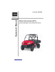
Operator’s Manual Form No. 3394-897 Utility Task Vehicle (UTV) Model No. UTV500AAC00000 - Serial No. 4UF15MPV3FT307514 and Up Model No. UTV700AAC00000 - Serial No. 4UF15MPV2FT307524 and Up Register at www.Toro.
This vehicle can be hazardous to operate. A collision or rollover can occur quickly, even during what you think are routine maneuvers such as driving or turning on flat terrain, driving on hills, or crossing obstacles, if you fail to take proper precautions. For your safety, understand and follow all the warnings contained in this Operator’s Manual and the labels on this vehicle. Keep this Operator’s Manual with this vehicle at all times.
Foreword Congratulations and thank you for purchasing a Toro UTV500/UTV700. Built with American engineering and manufacturing know-how, it is designed to provide superior ride, comfort, utility, and dependable service. You have chosen a quality Toro product designed and manufactured to give dependable service. Be sure, as the owner/ operator of this vehicle, to become thoroughly familiar with its basic operation, maintenance, and storage procedures.
Table of Contents Foreword.................................................1 Parts and Accessories ..........................1 DIVISION I - SAFETY Safety Alert.............................................4 Warning and Instructional Labels .....5-6 Location of Parts and Controls ............7 Warnings ...........................................8-16 DIVISION II OPERATION/ MAINTENANCE Specifications ......................................17 Vehicle Operation ...........................
DIVISION I - SAFETY This vehicle is not a toy and can be hazardous to operate. NOTE: To view important safety information, please log on to www.toro.com/en-us/safety (USA) or www.toro.com/en-ca/safety (Canada). • Always go slowly and be extra careful when operating on unfamiliar terrain. Always be alert to changing terrain conditions when operating this vehicle. • Never operate on excessively rough, slippery, or loose terrain. • Always follow proper procedures for turning as described in this manual.
Safety Alert You should be aware that THIS VEHICLE IS NOT A TOY AND CAN BE HAZARDOUS TO OPERATE. This vehicle handles differently from other vehicles, including motorcycles and cars. A collision or rollover can occur quickly, even during what you think are routine maneuvers such as turning, driving on hills, and going over obstacles, if you fail to take proper precautions. TO AVOID SERIOUS INJURY OR DEATH: * Always read the Operator’s Manual carefully and follow the operating procedures described.
Warning and Instructional Labels HDX191D Pour commander des Etiquettes de Mise en Garde gratuites, voyez votre détailant de autorisé VTT Toro pour le numéro de pièce 1436-444. ! WARNING Indicates a hazardous situation which, if not avoided, could result in death or serious injury.
Warning and Instructional Labels HDX189A 6 ! WARNING Indicates a hazardous situation which, if not avoided, could result in death or serious injury.
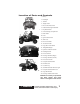
Location of Parts and Controls 1. Battery 2. Headlights 3. Tool Kit 4. Tailgate Latch 5. Reverse Override Switch 6. Outboard Passenger Hand Hold HDX184A 7. Hip Restraint Bar 8. In-Dash Storage Compartment 9. Brake Pedal 10. Fuses 11. Ignition/Start Switch 12. Shift Lever 13. DC Power Outlets TC001A 14. Accelerator Pedal 15. Cargo Box Latch Handle 16. Taillight/Brakelight 17. Operator’s Manual Location 18. Headlight Switch 19. Driver Seat Belt 20. Passenger Seat Belt (Right) TC002A 21.
Warnings ! WARNING POTENTIAL HAZARD Operating this vehicle without proper instruction. WHAT CAN HAPPEN The risk of an accident is greatly increased if the operator does not know how to operate this vehicle properly in different situations and on different types of terrain. HOW TO AVOID THE HAZARD All operators of this vehicle must read and understand this Operator’s Manual and all warning and instruction labels prior to operating this vehicle.
Warnings ! WARNING POTENTIAL HAZARD Operating this vehicle without wearing an approved helmet, eye protection, and protective clothing. WHAT CAN HAPPEN Operating without an approved helmet increases your chances of a serious head injury or death in the event of an accident. Operating without eye protection can result in an accident and increases your chances of a serious injury in the event of an accident.
Warnings ! WARNING POTENTIAL HAZARD Operating or riding in the vehicle without occupant side restraints properly secured. WHAT CAN HAPPEN Serious injury or death. Occupants or their body parts can strike objects outside the vehicle, be crushed by the vehicle, or fall out of the vehicle during maneuvers or in the event of an accident. HOW TO AVOID THE HAZARD Do not remove the occupant side restraints.
Warnings ! WARNING POTENTIAL HAZARD Attempting wheelies, jumps, and other stunts. WHAT CAN HAPPEN Increases the chance of an accident including a rollover. HOW TO AVOID THE HAZARD Never attempt stunts, such as wheelies or jumps. Don’t try to show off. ! WARNING POTENTIAL HAZARD Failure to inspect this vehicle before operating. Failure to properly maintain this vehicle. WHAT CAN HAPPEN Increases the possibility of an accident or equipment damage.
Warnings ! WARNING POTENTIAL HAZARD Failing to use care in turns; turning too sharply or aggressively. WHAT CAN HAPPEN The vehicle could go out of control causing a collision, tip over, or rollover. HOW TO AVOID THE HAZARD Always follow proper procedures for turning as described in this Operator’s Manual. Practice turning at slow speeds before attempting to turn at faster speeds. Do not turn at excessive speed or too sharply for the conditions and for your experience level.
Warnings ! WARNING POTENTIAL HAZARD Climbing hills improperly. WHAT CAN HAPPEN Could cause loss of control or cause the vehicle to overturn. HOW TO AVOID THE HAZARD Always follow proper procedures for climbing hills as described in this Operator’s Manual. Always check the terrain carefully before you start up any hill. Never climb hills with slippery or loose surfaces. Never open the throttle suddenly or make sudden gear changes. The vehicle could flip over backwards.
Warnings ! WARNING POTENTIAL HAZARD Improperly operating in reverse. WHAT CAN HAPPEN You could hit an obstacle or person behind you, resulting in serious injury or death. HOW TO AVOID THE HAZARD Before you engage reverse gear, make sure there are no obstacles or people behind you. When it is safe to proceed, go slowly. ! WARNING POTENTIAL HAZARD Improperly operating over obstacles. WHAT CAN HAPPEN Could cause loss of control or a collision. Could cause the vehicle to overturn.
Warnings ! WARNING POTENTIAL HAZARD Overloading the vehicle or carrying or towing cargo improperly. WHAT CAN HAPPEN Could cause changes in handling, which could lead to an accident. HOW TO AVOID THE HAZARD Never exceed the stated load capacity for this vehicle. Cargo should be properly distributed and securely attached. Reduce speed when carrying cargo or pulling a trailer. Allow greater distance for braking. Always follow the instructions in this Operator’s Manual for carrying cargo or pulling a trailer.
Warnings ! WARNING POTENTIAL HAZARD Operating through or over thick or sharp brush, timber, debris, or rocks. WHAT CAN HAPPEN Serious injury or death. Brush, branches, debris, and rocks can enter or penetrate the passenger compartment and strike occupants. Running over sharp branches, rocks, or other large objects can also cause loss of control. HOW TO AVOID THE HAZARD Be alert. Slow down. Wear all recommended protective gear specified in this Operator’s Manual.
DIVISION II - OPERATION/ MAINTENANCE Specifications ENGINE Type Four-Cycle/Liquid Cooled Bore x Stroke 89 mm x 71.12 mm (3.5 x 2.8 in.) - 500 102 mm x 85 mm (4.01 x 3.4 in.) - 700 Displacement 442 cc (27 cu in.) - 500 695 cc (42.4 cu in.) - 700 Spark Plug Type NGK CR7E - 500 NGK CPR8E - 700 Spark Plug Gap 0.7-0.8 mm (0.028-0.031 in.) - 500 0.5-0.6 mm (0.019-0.024 in.) - 700 Brake Type Hydraulic Disc/Rear Driveline - 500 Four Wheel Hydraulic - 700 CHASSIS Length (Overall) 327.6 cm (129.0 in.
Vehicle Operation Pre-Start/Pre-Operation Checklist Item Remarks Brake System Pedal firm - near top of travel. Fluid at proper level. Check for fluid leaks. Controls Steering free - no binding - no excessive free-play. Shift lever in park. Accelerator free - no binding - returns to idle position. Fluids Coolant level to the bottom of the stand pipe in the radiator neck. Check oil level. Gas tank full of recommended gasoline. Differential/rear drive at proper level. Check for fluid leaks.
Starting the Vehicle Shifting the Always start with the vehicle on a flat, Continuously Variable level surface. Carbon monoxide poison- Transmission (CVT) ing can kill you, so keep the vehicle outCAUTION side while it’s running. Follow these steps to start it up: Always come to a complete stop attempting to shift from one 1. Step into the vehicle and sit down; then before range to the other or into reverse or fasten the operator seat belt and the park.
CAUTION CAUTION Always shift into low range when operating on wet or uneven terrain, when towing or pushing heavy loads, and when using a plow. Failure to follow this caution may result in premature V-belt failure or in damage to related drive system components. Never increase engine speed above idle RPM when in park or belt damage will occur. 3. To select reverse gear from park, move the shift lever upward one position until the letter “R” is displayed on the LCD.
! WARNING Use only DOT 4 approved brake fluid. Never substitute or mix different types or grades of brake fluid. Brake loss can result. Check brake fluid level and pad wear before each use. Brake loss can result in serious injury or death. Parking Parking involves following the previous rules for braking; then: 1. After the vehicle stops, shift into park. 2. Then turn off the ignition. ! WARNING Avoid parking this vehicle on hills.
2. Prior to descending the hill, shift into low range and release the accelerator to allow maximum engine braking. Do not use four-wheel drive when descending a hill. Engine braking can cause the front wheels to slide reducing steering control. NOTE: If there is any question about your ability to cross the obstacle safely, you should turn around if the ground is flat and you have room or back up until you find a less difficult path.
NOTE: Light pedal pressure or pumping the brakes for a short distance will aid in drying the brakes. Crossing Roads It may be necessary to cross a road or highway. If so, note the following guidelines. 1. Stop completely on the shoulder of the road. 2. Check both directions for traffic. 3. Crossing near a blind corner or intersection is dangerous; avoid it if at all possible. 4. Drive straight across to the opposite shoulder. 2.
General Information Control Locations and Functions Ignition Switch Key Two keys come with this vehicle. Keep the spare key in a safe place. Ignition Switch The ignition switch has three positions. TC037 Drive Select Switch 500 ATV-0056A OFF position — All electrical circuits except the accessory are off. The engine will not start. The key can be removed in this position. NOTE: The accessory plugs are powered by the battery at all times.
To select 2WD, depress the bottom of the switch. To select 4WD, move the switch to the middle position. To engage the differential lock, slide the switch latch slightly downward while pressing the top of the switch forward. Reverse Override Switch This vehicle is equipped with a reverse speed limiter system. When additional RPM is needed in reverse, depress and hold the override switch located on the dash.
NOTE: To remove the seat base and seat back, first remove the four screws securing the seat back and set the seat back aside. Remove the screws securing the seat base and set the seat base aside. Seat Belts This vehicle is equipped with seat belts for the operator and two passengers. To fasten and release the seat belt properly, use the following procedure. HDX187A 1.
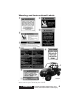
HDX112A HDX115A 5. Remove the stake pocket retaining bolts, jam nuts, and forward tie bolt clip nuts and secure in a safe place with the machine screws and bushings from the tailgate. HDX113A 3. Open the tailgate and remove the machine screws securing the stopcables to the tailgate. Note the correct orientation of the bushings to the cable ends and tailgate. HDX116A To convert flat-bed to cargo box, use the following procedure. 1.
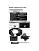
HDX118A HDX113A 3. Set the left and right cargo box side panels into place on the cargo bed engaging the stakes into the side pockets. 4. Install the left and right side clip nuts onto the frame; then install and tighten the forward tie bolts securely. HDX122 6. Secure the tailgate stop-cables to the tailgate with the machine screws and bushings making sure the bushing engages the cable as shown. Tighten to 2.7 N-m (24 in.-lb). HDX116A 5.
Cargo Box Latch Handles HDX094A CAUTION TC008A When using ratchet-type straps, do not over tighten or damage to the cargo box could occur. 1. To raise the cargo box, lift the latch handle upward; then raise the cargo box. NOTE: Always refer to the Load Capacity Ratings chart in this manual when loading and hauling cargo. Tailgate Latches HDX094 2. To lower the cargo box, use the box handle to push down firmly on the front of the box.
The LCD will go blank except the word VOLT will flash on the LCD whenever a low voltage (<9 DC volts) or a high voltage (>16 DC volts) is detected. When voltage returns to normal, the gauge must be reset by turning the ignition key to the OFF position and then to the ON position. A. With the ignition switch ON, press and release the Mode Button until the Clock/Engine Hour Meter is displayed; then (if necessary) press and release the Set/Reset Button to the clock display. B.
11. High Beam Indicator - Appears when the headlights are on high beam. 12. Temperature Indicator - The speedometer/tachometer needle will sweep full scale and the LCD will go blank except the high temperature icon will flash. After 30 seconds, the speedometer/ tachometer needle and LCD will return to normal, but the temperature icon will continue to flash. The icon should not be visible during normal operation. 2. From the left side, unscrew the oil level stick and wipe it with a clean cloth. 500 13.
Trailering and Towing 700 HDX022A CAUTION HDX062A This vehicle is equipped with a frameDo not overfill the engine with oil. mounted receiver (front and rear) for a Always make sure the oil level is standard 5.1 cm (2 in.) receiver hitch. within operating range. The standard receiver hitch must be purchased separately. Load Capacity Ratings This vehicle must always be loaded in ! WARNING accordance with the Load Capacity RatMake sure that the load in the trailer is ings chart.
! WARNING CAUTION Driving this vehicle without extra caution when towing a trailer will be hazardous. Trailer towing can affect the handling and braking of the vehicle. Tow only at low speeds and never exceed 16 kph (10 mph). Avoid sudden accelerations and stopping of the vehicle. Do not make quick maneuvers. Avoid uneven surfaces and do not tow on hills. Never carry passengers in a trailer unless the trailer is designed for such use and has a rigid tow bar.
Gasoline-Oil-Lubricant Recommended Gasoline The recommended gasoline to use in this vehicle is 87 minimum octane regular unleaded. In many areas, oxygenates are added to the gasoline. Oxygenated gasolines containing up to 10% ethanol or 5% methane are acceptable gasolines. When using ethanol blended gasoline, it is not necessary to add a gasoline antifreeze since ethanol will prevent the accumulation of moisture in the fuel system. CAUTION Do not use white gas.
ROV353A During the first 10 hours of operation, always use less than ½ throttle. Varying the engine RPM during the break-in period allows the components to “load” (aiding the engine/transmission component mating process) and then “unload” (allowing components to cool). Although it is essential to place some stress on the engine components during break-in, care should be taken not to overload the engine too often. Do not pull a trailer during the break-in period.
General Maintenance NOTE: Proper maintenance of the ROV is important for optimum performance. Follow the Maintenance Schedule and all ensuing maintenance and care instructions/information. If, at any time, abnormal noises, vibrations, or improper functioning of any component of this vehicle is detected, DO NOT OPERATE THE VEHICLE. Take the vehicle to an authorized Toro ROV dealer for inspection and adjustment or repair.
Maintenance Schedule Item Page Initial Every Every Every 160 km 160 km 480 km 800 km (100 miles) (100 miles) (300 miles) (500 miles) Battery 43 I * Engine nuts and bolts — I I * Valve clearance — I I Spark plug 45 I I 45 I Replace every 6500 km (4000 miles) or 18 months Liquid cooling system 38 I Inspect every time before operating Gas hoses 31 I Inspect every time before operating 31 Replace every 2 years Engine/transmission oil and filter 39 R R** Air filter 46 I I G
Liquid Cooling System NOTE: Debris in the engine compartment or packed between the cooling fins of the radiator can reduce cooling capability. Using a garden hose, wash the radiator to remove any debris preventing air flow. CAUTION Do not use a pressure washer to clean the radiator core. The pressure may bend or flatten the fins causing restricted air flow, and electrical components on the radiator could be damaged. Use only a garden hose with spray nozzle at normal tap pressure.
To adjust the spring force on the these shock absorbers, rotate the pre-load adjustment sleeve with a suitable spanner wrench until desired spring tension is achieved. Position Spring Force 1 Setting Load Soft Light 2 3 4 5 Stronger Stiff Heavy General Lubrication Cables None of the cables require lubrication; however, it is advisable to lubricate the ends of the cables periodically with a good cable lubricant. Cargo Box Latches Periodically apply a light coat of grease to the latches and pins.
4. Remove the drain plug from the bottom of the engine and drain the oil into a drain pan. 7. Install the engine drain plug and tighten to 22 N-m (16 ft-lb). Pour the recommended oil in the fill hole (700) or oil level stick opening (500). Install the oil fill cap (700) or the oil level stick (500). 8. Start the engine (while the vehicle is outside on level ground) and allow it to idle for a few minutes. 9. Turn the engine off and wait approximately one minute.
3. Drain the lubricant into a drain pan by Brake Fluid removing the drain plug from the front differential and rear drive. HDX081A CF107A 1. Check the brake fluid level in the brake fluid reservoir. The fluid level must be maintained between the MAX and MIN level marks. If the level in the reservoir is low, add DOT 4 approved brake fluid. NOTE: The brake fluid reservoir is located on top of the master cylinder under the hood. 2. Press the brake pedal several times to check for firmness. CF106A 3.
3. If thickness of either brake pad is less Ball Joint Boots (Upper than 1.0 mm (0.039 in.), take the and Lower/Right and Left) vehicle to an authorized Toro ROV dealer to have brake pads replaced. CC791 PR376B 4. Install the wheel; then using a crisscross pattern, tighten the wheel nuts in 27 N-m (20 ft-lb) increments to the final torque shown in the table below. Steel Wheel 54 N-m (40 ft-lb) Aluminum Wheel (Black Nuts) 80 N-m (60 ft-lb) Aluminum Wheel (Chrome Nuts) 108 N-m (80 ft-lb) 1.
Drive Axle Boots PR942 CC793 After being in service, batteries require 1. Inspect the front and rear drive axle regular cleaning and recharging in order boots for cracks, tears, or perforations. to deliver peak performance and maximum service life. The following proce2. If boot damage is present, contact an dure is recommended for cleaning and authorized Toro ROV dealer for ser- maintaining a sealed battery. Always read and follow instructions provided with vice. battery chargers and battery products.
NOTE: The sealing strip should NOT be removed and NO fluid should be added. 2. Be sure the charger and battery are in a well-ventilated area. Be sure the charger is unplugged from the 110volt electrical outlet. 3. Connect the red terminal lead from the charger to the positive terminal of the battery; then connect the black terminal lead of the charger to the negative terminal of the battery. 4. Plug the battery charger into a 110volt electrical outlet. 5.
Spark Plug This vehicle comes equipped with a specified spark plug. See the specifications chart for the correct spark plug. A light brown insulator indicates that the plug is correct. A white or dark insulator indicates that the engine may need to be serviced. Consult an authorized Toro ROV dealer if the plug insulator is not a light 0744-527 brown color. To help prevent cold weather fouling, make sure to thoroughly NOTE: Some jumper cables may be warm up the engine before operating.
1. Raise the cargo box; then gently NOTE: To access the air filter, squeeze the pre-filter cover and lift it raise the cargo box. up to expose the pre-filter. 1. Remove dirt and debris from around the filter housing. 2. Unsnap the four spring-clip fasteners and remove the air filter cover. HDX237A 2. Loosen the clamp securing the prefilter. HDX050A 3. Remove the two knobs securing the filter; then remove the metal holddown and filter. HDX235 3.
8. Squeeze the element to remove Draining V-Belt Cover excess oil. NOTE: If the vehicle has been driven through water, the V-belt CAUTION cover must be drained of any water. A torn air filter can cause damage to the engine. Dirt and dust may get inside the engine if the element is torn. Carefully examine the element for tears before and after cleaning it. Replace the element with a new one if it is torn. 1. Place the vehicle on a level surface. 2.
Tire Tread Condition 3. Elevate the vehicle. 4. Remove the lug nuts. 5. Remove the wheel. 6. Install the wheel; then using a crisscross pattern, tighten the wheel nuts in 27 N-m (20 ft-lb) increments to the final torque shown in the table below. 0732-649 The use of worn-out tires on this vehicle is very dangerous. A tire is considered to be worn out when the depth of the tread is less than 3 mm (1/8 in.). Be sure to replace the tires before reaching this minimum specification.
HDX238A HDX242 2. Remove the muffler by pulling it NOTE: If the screen or gasket is rearward out of the vehicle. damaged in any way, it must be replaced. 3. Remove the heat shield. 6. Install the exhaust pipe/spark arrester assembly and secure with the three cap screws. Tighten to 6.8 N-m (60 in.-lb). 7. Install the heat shield and tighten the fasteners to 8.1 N-m (72 in.-lb). 8. Install the muffler and secure it to the exhaust pipe with the two springs.
3. Install the new bulb into the housing; then install the housing and rotate it completely clockwise. 3. Using the measurements obtained in step 2, make horizontal marks on the aiming surface. 4. Install the wiring harness connector. To replace the taillight/brakelight bulb, use the following procedure. 4. Make vertical marks which intersect the horizontal marks on the aiming surface directly in front of the headlights. 1.
NOTE: Extra fuses are located A basic tool kit located under the seat (passenger side) is provided with this inside the fuse cover. vehicle. Maintain the tool kit with the vehicle at all times. TC035 Electrical Output Terminals TC032 Seat Belts Two output terminals for electrical accessories are located on the front and rear Inspect the seat belts for frayed or torn edges. Check that the belts extend and wiring harnesses.
Preparation for Storage Toro recommends the following procedure to prepare the vehicle for storage. An authorized Toro ROV dealer should perform this service; however, the owner/ operator may perform this service if desired. CAUTION Prior to storing this vehicle, it must be properly serviced to prevent rusting and component deterioration. 1. Clean the seat cushions with a damp cloth and allow to dry. 2.
Preparation after Storage Taking this vehicle out of storage and correctly preparing it will assure many miles and hours of trouble-free riding. Toro recommends the following procedure. 1. Clean the vehicle thoroughly. 2. Clean the engine. Remove the cloth from the exhaust system. 3. Check all control wires and cables for signs of wear or fraying. Replace if necessary. 4. Change the engine/transmission oil and filter. 5. Check the coolant level and add properly mixed coolant as necessary. 6.
Limited Warranty The Toro Company (hereinafter referred to as Toro) extends a limited warranty as described below on each new Toro ROV it assembles and on each genuine Toro ROV part and accessory assembled and sold by an authorized Toro ROV dealer. The limited warranty on a Toro ROV is extended to the original retail purchaser for the time periods described below; however, the balance of the remaining warranty may be transferred to another party.
Warranty Procedure/Owner Responsibility At the time of sale, an Owner Registration form is to be completed by the selling dealer and consumer. The receipt of the form by Toro is a condition precedent to warranty coverage. It is the selling dealer’s responsibility to retain and/or submit appropriate copies of the form to the appropriate place(s) to initiate warranty coverage.
U.S. EPA Emission Control Statement/Warranty Coverage (U.S. Only) STATEMENT/WARRANTY The Toro Company warrants to the original retail purchaser, and each subsequent purchaser, that all U.S. EPA-certified Toro ROV’s are designed, built, and equipped to conform to all U.S. EPA Emission Control Regulations. Please read the following information completely. Your authorized Toro ROV dealer will repair or replace any defective emission-related component at no cost to you during the warranty period.
Maintenance Record DATE MILEAGE SERVICE PERFORMED/NOTES 57
NOTES 58
Change of Address, Ownership, or Warranty Transfer The Toro Company keeps on file the current name and address of the owner of this vehicle. This allows Toro to reach the current owner with any important safety information which may be necessary to protect customers from personal injury or property damage. Please make sure a copy of this form is completed and returned to Toro if you move or if the vehicle is sold to another party.
Fold Back CHANGE OF ADDRESS/OWNERSHIP The Toro Company Warranty Dept. 8111 Lyndale Ave.
Identification Numbers Record This vehicle has three identification numbers: Model Number, Serial Number, and Engine Serial Number (ESN). These numbers are required by the dealer to complete warranty claims properly. No warranty will be allowed by Toro if the numbers are removed or mutilated in any way. Always provide the name, Model Number, Serial Number, and ESN when contacting an authorized Toro ROV dealer for parts, service, accessories, or warranty.
©2015 Toro Company Form No. 3394-897 Rev.