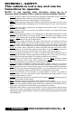
This vehicle can be hazardous to operate. A collision or rollover can occur quickly, even during what you think are routine maneuvers such as driving or turning on flat terrain, driving on hills, or crossing obstacles, if you fail to take proper precautions. For your safety, understand and follow all the warnings contained in this Operator’s Manual and the labels on this vehicle. Keep this Operator’s Manual with this vehicle at all times.
Foreword Congratulations and thank you for purchasing a Toro UTV700. Built with American engineering and manufacturing know-how, it is designed to provide superior ride, comfort, utility, and dependable service. You have chosen a quality Toro product designed and manufactured to give dependable service. Be sure, as the owner/ operator of this vehicle, to become thoroughly familiar with its basic operation, maintenance, and storage procedures.
Table of Contents Foreword................................................. 1 Parts and Accessories .......................... 1 DIVISION I - SAFETY Safety Alert............................................. 4 Warning and Instructional Labels .....5-6 Location of Parts and Controls ............ 7 Warnings ...........................................8-16 DIVISION II OPERATION/ MAINTENANCE Specifications ...................................... 17 Vehicle Operation ...........................
DIVISION I - SAFETY This vehicle is not a toy and can be hazardous to operate. NOTE: To view important safety information, please log on to www.toro.com/en-us/safety (USA) or www.toro.com/en-ca/safety (Canada). • Always go slowly and be extra careful when operating on unfamiliar terrain. Always be alert to changing terrain conditions when operating this vehicle. • Never operate on excessively rough, slippery, or loose terrain. • Always follow proper procedures for turning as described in this manual.
Safety Alert You should be aware that THIS VEHICLE IS NOT A TOY AND CAN BE HAZARDOUS TO OPERATE. This vehicle handles differently from other vehicles, including motorcycles and cars. A collision or rollover can occur quickly, even during what you think are routine maneuvers such as turning, driving on hills, and going over obstacles, if you fail to take proper precautions. TO AVOID SERIOUS INJURY OR DEATH: * Always read the Operator’s Manual carefully and follow the operating procedures described.
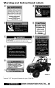
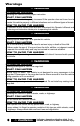
Warning and Instructional Labels HDX191E Pour commander des Etiquettes de Mise en Garde gratuites, voyez votre détailant de autorisé VTT Toro pour le numéro de pièce 2436-306. ! WARNING Indicates a hazardous situation which, if not avoided, could result in death or serious injury.
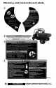
Warning and Instructional Labels HDX189A 6 ! WARNING Indicates a hazardous situation which, if not avoided, could result in death or serious injury.
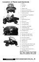
Location of Parts and Controls 1. Battery 2. Headlights 3. Tool Kit 4. Tailgate Latch 5. Reverse Override Switch 6. Outboard Passenger Hand Hold HDX184A 7. Hip Restraint Bar 8. In-Dash Storage Compartment 9. Brake Pedal 10. Fuses 11. Ignition/Start Switch 12. Shift Lever 13. DC Power Outlets TC001B 14. Accelerator Pedal 15. Cargo Box Latch Handle 16. Taillight/Brakelight 17. Operator’s Manual Location 18. Headlight Switch 19. Driver Seat Belt 20. Passenger Seat Belt (Right) TC002A 21.
Warnings ! WARNING POTENTIAL HAZARD Operating this vehicle without proper instruction. WHAT CAN HAPPEN The risk of an accident is greatly increased if the operator does not know how to operate this vehicle properly in different situations and on different types of terrain. HOW TO AVOID THE HAZARD All operators of this vehicle must read and understand this Operator’s Manual and all warning and instruction labels prior to operating this vehicle.
Warnings ! WARNING POTENTIAL HAZARD Operating this vehicle without wearing an approved helmet, eye protection, and protective clothing. WHAT CAN HAPPEN Operating without an approved helmet increases your chances of a serious head injury or death in the event of an accident. Operating without eye protection can result in an accident and increases your chances of a serious injury in the event of an accident.
Warnings ! WARNING POTENTIAL HAZARD Operating or riding in the vehicle without occupant side restraints properly secured. WHAT CAN HAPPEN Serious injury or death. Occupants or their body parts can strike objects outside the vehicle, be crushed by the vehicle, or fall out of the vehicle during maneuvers or in the event of an accident. HOW TO AVOID THE HAZARD Do not remove the occupant side restraints.
Warnings ! WARNING POTENTIAL HAZARD Attempting abrupt maneuvers, sideways sliding, skidding, fishtailing, or donuts. WHAT CAN HAPPEN Increases the chance of an accident including a rollover. HOW TO AVOID THE HAZARD Never attempt abrupt maneuvers, sideways sliding, skidding, fishtailing, or donuts. Don’t try to show off. ! WARNING POTENTIAL HAZARD Failure to inspect this vehicle before operating. Failure to properly maintain this vehicle.
Warnings ! WARNING POTENTIAL HAZARD Failing to use care in turns; turning too sharply or aggressively. WHAT CAN HAPPEN The vehicle could go out of control causing a collision, tip over, or rollover. HOW TO AVOID THE HAZARD Always follow proper procedures for turning as described in this Operator’s Manual. Practice turning at slow speeds before attempting to turn at faster speeds. Do not turn at excessive speed or too sharply for the conditions and for your experience level.
Warnings ! WARNING POTENTIAL HAZARD Climbing hills improperly. WHAT CAN HAPPEN Could cause loss of control or cause the vehicle to overturn. HOW TO AVOID THE HAZARD Always follow proper procedures for climbing hills as described in this Operator’s Manual. Always check the terrain carefully before you start up any hill. Never climb hills with slippery or loose surfaces. Never open the throttle suddenly or make sudden gear changes. The vehicle could flip over backwards.
Warnings ! WARNING POTENTIAL HAZARD Improperly operating in reverse. WHAT CAN HAPPEN You could hit an obstacle or person behind you, resulting in serious injury or death. HOW TO AVOID THE HAZARD Before you engage reverse gear, make sure there are no obstacles or people behind you. When it is safe to proceed, go slowly. ! WARNING POTENTIAL HAZARD Improperly operating over obstacles. WHAT CAN HAPPEN Could cause loss of control or a collision. Could cause the vehicle to overturn.
Warnings ! WARNING POTENTIAL HAZARD Overloading the vehicle or carrying or towing cargo improperly. WHAT CAN HAPPEN Could cause changes in handling, which could lead to an accident. HOW TO AVOID THE HAZARD Never exceed the stated load capacity for this vehicle. Cargo should be properly distributed and securely attached. Reduce speed when carrying cargo or pulling a trailer. Allow greater distance for braking. Always follow the instructions in this Operator’s Manual for carrying cargo or pulling a trailer.
Warnings ! WARNING POTENTIAL HAZARD Operating through or over thick or sharp brush, timber, debris, or rocks. WHAT CAN HAPPEN Serious injury or death. Brush, branches, debris, and rocks can enter or penetrate the passenger compartment and strike occupants. Running over sharp branches, rocks, or other large objects can also cause loss of control. HOW TO AVOID THE HAZARD Be alert. Slow down. Wear all recommended protective gear specified in this Operator’s Manual.
DIVISION II - OPERATION/ MAINTENANCE Specifications ENGINE Type Four-Cycle/Liquid Cooled Bore x Stroke 102 mm x 85 mm (4.01 x 3.4 in.) Displacement 695 cc (42.4 cu in.) Spark Plug Type NGK CPR8E Spark Plug Gap 0.5-0.6 mm (0.019-0.024 in.) Brake Type Four Wheel Hydraulic CHASSIS Length (Overall) 327.6 cm (129.0 in.) Height (Overall) 200.6 cm (79.0 in.) Width (Overall) 152.4 cm (60 in.) Suspension Travel (Front/Rear) 25.4 cm (10 in.
Vehicle Operation Pre-Start/Pre-Operation Checklist Item Remarks Brake System Pedal firm - near top of travel. Fluid at proper level. Check for fluid leaks. Controls Steering free - no binding - no excessive free-play. Shift lever in park. Accelerator free - no binding - returns to idle position. Fluids Coolant level to the bottom of the stand pipe in the radiator neck. Check oil level. Gas tank full of recommended gasoline. Differential/rear drive at proper level. Check for fluid leaks.
Starting the Vehicle Shifting the Always start with the vehicle on a flat, Continuously Variable level surface. Carbon monoxide poison- Transmission (CVT) ing can kill you, so keep the vehicle outCAUTION side while it’s running. Follow these steps to start it up: Always come to a complete stop attempting to shift from one 1. Step into the vehicle and sit down; then before range to the other or into reverse or fasten the operator seat belt and the park.
CAUTION CAUTION Always shift into low range when operating on wet or uneven terrain, when towing or pushing heavy loads, and when using a plow. Failure to follow this caution may result in premature V-belt failure or in damage to related drive system components. Never increase engine speed above idle RPM when in park or belt damage will occur. 3. To select reverse gear from park, move the shift lever upward one position until the letter “R” is displayed on the LCD.
! WARNING Use only DOT 4 approved brake fluid. Never substitute or mix different types or grades of brake fluid. Brake loss can result. Check brake fluid level and pad wear before each use. Brake loss can result in serious injury or death. Parking Parking involves following the previous rules for braking; then: 1. After the vehicle stops, shift into park. 2. Then turn off the ignition. ! WARNING Avoid parking this vehicle on hills.
2. Prior to descending the hill, shift into low range and release the accelerator to allow maximum engine braking. Do not use four-wheel drive when descending a hill. Engine braking can cause the front wheels to slide reducing steering control. NOTE: If there is any question about your ability to cross the obstacle safely, you should turn around if the ground is flat and you have room or back up until you find a less difficult path.
NOTE: Light pedal pressure or pumping the brakes for a short distance will aid in drying the brakes. Crossing Roads It may be necessary to cross a road or highway. If so, note the following guidelines. 1. Stop completely on the shoulder of the road. 2. Check both directions for traffic. 3. Crossing near a blind corner or intersection is dangerous; avoid it if at all possible. 4. Drive straight across to the opposite shoulder. 2.
General Information Control Locations and Functions Ignition Switch Key Two keys come with this vehicle. Keep the spare key in a safe place. Ignition Switch The ignition switch has three positions. TC037 Drive Select Switch ATV-0056A OFF position — All electrical circuits except the accessory are off. The engine will not start. The key can be removed in this position. NOTE: The accessory plugs are powered by the battery at all times.
NOTE: When the differential lock is engaged, the indicator light will be illuminated. ! WARNING The differential lock is intended for use where minimum traction is available. NEVER EXCEED 16 kph (10 MPH) with the front differential lock engaged. Maneuverability and handling characteristics will differ with the differential lock engaged. Control loss can result in serious injury or death. Foot Brake The foot brake is the only service brake, and it should be applied whenever braking is needed.
NOTE: The vehicle must be in 4WD to activate the reverse override. ! WARNING Never activate the override switch while the throttle is open as a loss of control could result. Accelerator Pedal Press down on the pedal to increase engine RPM and vehicle speed; release the pedal to decrease engine RPM and vehicle speed. NOTE: This vehicle is equipped with an RPM limiter that retards ignition timing when maximum RPM is approached.
HDX188 Cargo Box The cargo box on this ROV can be converted to a “flat-bed” cargo platform. To convert your cargo box to a flat-bed, use the following procedure. HDX113A 3. Open the tailgate and remove the machine screws securing the stopcables to the tailgate. Note the correct orientation of the bushings to the cable ends and tailgate. 1. Remove all cargo from the box; then remove the left and right forward tie bolts. HDX114A 4.
5. Remove the stake pocket retaining bolts, jam nuts, and forward tie bolt clip nuts and secure in a safe place with the machine screws and bushings from the tailgate. 4. Install the left and right side clip nuts onto the frame; then install and tighten the forward tie bolts securely. HDX116A HDX116A To convert flat-bed to cargo box, use the following procedure. 1. Set the tailgate into position in the cargo bed; then lift the cargo bed making sure the tailgate clears any receiver hitch attachments. 5.
6. Secure the tailgate stop-cables to the tailgate with the machine screws and bushings making sure the bushing engages the cable as shown. Tighten to 2.7 N-m (24 in.-lb). 1. To open the tailgate, pull the latch handles (located on the end of the tailgate). 2. To close the tailgate, lift up and push forward firmly. Hook the latch bails and push the handles forward over center. HDX123 TC009 Cargo Box Tie Downs The cargo box has numerous tie down Cargo Box Latch Handles locations around the top perimeter.
Power Steering Certain vehicles were produced with an Electronic Power Steering (EPS) system to reduce steering effort and driver fatigue over a broad range of operating conditions. The EPS system engages when the ignition switch is turned to the ON position and disengages after approximately five minutes (to conserve battery power) if the engine is not running. This system is entirely maintenance-free: no adjustment or servicing is required.
The LCD will go blank except the word VOLT will flash on the LCD whenever a low voltage (<9 DC volts) or a high voltage (>16 DC volts) is detected. When voltage returns to normal, the gauge must be reset by turning the ignition key to the OFF position and then to the ON position. A. With the ignition switch ON, press and release the Mode Button until the Clock/Engine Hour Meter is displayed; then (if necessary) press and release the Set/Reset Button to the clock display. B.
11. High Beam Indicator - Appears when the headlights are on high beam. 2. From the left side, unscrew the oil level stick and wipe it with a clean cloth. 12. Temperature Indicator - The speedometer/tachometer needle will sweep full scale and the LCD will go blank except the high temperature icon will flash. After 30 seconds, the speedometer/ tachometer needle and LCD will return to normal, but the temperature icon will continue to flash. The icon should not be visible during normal operation. 13.
Load Capacity Ratings This vehicle must always be loaded in accordance with the Load Capacity Ratings chart. Under no circumstances should the Vehicle Load Capacity or the Gross Vehicle Weight (GVW) rating ever be exceeded. ! WARNING Overloading this vehicle could result in loss of control resulting in serious injury or death. This vehicle is equipped with a framemounted receiver (front and rear) for a standard 5.1 cm (2 in.) receiver hitch. The standard receiver hitch must be purchased separately.
Transporting NOTE: When transporting the vehicle, make sure the vehicle is in park. This vehicle must be transported in its normal operating position (on all four wheels) and secured with hold-down straps in the proper areas. Shown is the minimum number of hold-down straps to be used. ! WARNING Use extreme caution when operating a machine on a ramp. Ensure that the ROPS will clear the top of an enclosed trailer. Use only a full-width ramp; do not use individual ramps for each side of the machine.
When using ethanol blended gasoline, it is not necessary to add a gasoline antifreeze since ethanol will prevent the accumulation of moisture in the fuel system. CAUTION Do not use white gas. Only recommended gasoline additives should be used. Recommended Engine/ Transmission Oil CAUTION Any oil used in place of the recommended oil could cause serious engine damage. Do not use oils which contain graphite or molybdenum additives. These oils can adversely affect clutch operation.
Tighten the gas tank cap securely after When the engine starts, allow it to warm up filling the tank. properly. Idle the engine several minutes until the engine has reached normal operating temperature. Do not idle the engine for ! WARNING excessively long periods of time. Do not overfill the gas tank. Engine Break-In Burnishing Brake Pads Brake pads must be burnished to achieve After the completion of the break-in full braking effectiveness.
General Maintenance NOTE: Proper maintenance of the ROV is important for optimum performance. Follow the Maintenance Schedule and all ensuing maintenance and care instructions/information. If, at any time, abnormal noises, vibrations, or improper functioning of any component of this vehicle is detected, DO NOT OPERATE THE VEHICLE. Take the vehicle to an authorized Toro ROV dealer for inspection and adjustment or repair.
Maintenance Schedule Item Page Initial Every Every Every 160 km 160 km 480 km 800 km (100 miles) (100 miles) (300 miles) (500 miles) Battery 44 I * Engine nuts and bolts — I I * Valve clearance — I I Spark plug 46 I I 46 I Replace every 6500 km (4000 miles) or 18 months Liquid cooling system 39 I Inspect every time before operating Gas hoses 32 I Inspect every time before operating 32 Replace every 2 years Engine/transmission oil and filter 40 R R** Air filter 47 I I G
Liquid Cooling System NOTE: Debris in the engine compartment or packed between the cooling fins of the radiator can reduce cooling capability. Using a garden hose, wash the radiator to remove any debris preventing air flow. CAUTION Do not use a pressure washer to clean the radiator core. The pressure may bend or flatten the fins causing restricted air flow, and electrical components on the radiator could be damaged. Use only a garden hose with spray nozzle at normal tap pressure.
To adjust the spring force on the these shock absorbers, rotate the pre-load adjustment sleeve with a suitable spanner wrench until desired spring tension is achieved. Position Spring Force 1 Setting Load Soft Light 2 3 4 5 Stronger Stiff Heavy General Lubrication Cables None of the cables require lubrication; however, it is advisable to lubricate the ends of the cables periodically with a good cable lubricant. Cargo Box Latches Periodically apply a light coat of grease to the latches and pins.
5. Use an appropriate oil filter wrench to remove the old oil filter and dispose of properly. Do not re-use oil filter. 11. Install the seat base, seat, and backrest. Front Differential And Rear Drive Gear Lubricant (Inspecting/Changing) Inspect and change the gear lubricant in each according to the Maintenance NOTE: Clean up any excess oil Schedule. When changing the lubricant, use the following procedure. after removing the filter. 1. Place the vehicle on level ground. 6.
NOTE: The brake fluid reservoir is located on top of the master cylinder under the hood. 2. Press the brake pedal several times to check for firmness. 3. If the pedal is not firm, the system must be bled. CF106A 4. After all the lubricant has been drained, install the drain plugs and tighten to 5 N-m (45 in.-lb). CAUTION NOTE: Take the vehicle to an authorized Toro ROV dealer for this service. CAUTION Be careful not to spill any fluid when filling the brake fluid reservoir.
4. Install the wheel; then using a crisscross pattern, tighten the wheel nuts in 27 N-m (20 ft-lb) increments to the final torque shown in the table below. Steel Wheel 54 N-m (40 ft-lb) Aluminum Wheel (Black Nuts) 80 N-m (60 ft-lb) Aluminum Wheel (Chrome Nuts) 108 N-m (80 ft-lb) 4. Check the ball joint for free-play by grasping the steering knuckle and turning it from side to side and up and down. 5.
After being in service, batteries require regular cleaning and recharging in order to deliver peak performance and maxi! WARNING mum service life. The following proceCALIFORNIA dure is recommended for cleaning and Proposition 65 Warning maintaining a sealed battery. Always read Battery posts, terminals, and related accessories contain lead and lead and follow instructions provided with compounds, chemicals known to the battery chargers and battery products.
4. Plug the battery charger into a 110volt electrical outlet. 5. Trickle charge the battery at 3 amps for 5-10 hours. If the battery becomes hot to the touch, stop charging. Resume after it has cooled. 6. Once the battery has reached full charge, unplug the charger from the 110-volt electrical outlet. NOTE: If, after charging, the battery does not perform to operator expectations, bring the battery to an authorized Toro ROV dealer for further troubleshooting. 3.
7. Attach one clamp of the negative (black) jumper cable to the negative (-) terminal (3) of the good battery (B); then attach the other clamp of the negative (black) jumper cable (4) to an unpainted metal surface (A) on the engine or frame well away from the dead battery and fuel system components. ! WARNING Never make the final connection to a battery as a spark could ignite hydrogen gases causing an explosion of the battery resulting in acid burns or blindness.
2. Loosen the clamp securing the pre-filter. 3. Remove the two knobs securing the filter; then remove the metal holddown and filter. HDX235 3. Remove the pre-filter assembly and wash thoroughly in warm, soapy water; then rinse and dry. 4. Install and secure with the clamp. Tighten securely; then with the pre-filter cover installed, lower the cargo box. Air Filter The air filter inside the air filter housing must be kept clean to provide good engine power and gas mileage.
Air Filter Housing Drains 5. Install the drain bolt and tighten securely. NOTE: The V-belt and pulleys should be inspected every 500 miles and the belt replaced (if necessary). Tires ! WARNING TC034A Always use the size and type of tires as specified. Refer to the specifications chart for proper tire inflation pressure, and always maintain proper tire inflation pressure. Inspect and squeeze the “duck bill” drain beneath the main housing for debris and Tire Tread Condition for proper sealing.
Tubeless Tire Repair Should a leak or flat tire occur due to a puncture, the tire may be repaired using a plug-type repair. If the damage is from a cut or if the puncture cannot be repaired using a plug, the tire must be replaced. When operating the vehicle in areas where transportation or service facilities are not readily available, it is strongly recommended to carry a plug-type repair kit and a tire pump along. Wheels 1.
5. Using a wire brush, clean the carbon deposits from the screen taking care not to damage the screen. 2. Grasp the bulb housing, turn it counterclockwise, and remove the housing. Remove the bulb. 3. Install the new bulb into the housing; then install the housing and rotate it completely clockwise. 4. Install the wiring harness connector. To replace the taillight/brakelight bulb, use the following procedure. HDX242 NOTE: If the screen or gasket is damaged in any way, it must be replaced. 6.
2. Measure the distance from the floor to the mid-point of each headlight. 3. Using the measurements obtained in step 2, make horizontal marks on the aiming surface. CAUTION Always replace a blown fuse with a fuse of the same type and rating. If the new fuse blows after a short period of use, consult an authorized Toro ROV dealer immediately. 4. Make vertical marks which intersect the horizontal marks on the aiming surface directly in front of the headlights. NOTE: Extra fuses are located 5.
Storage Compartment/ Tools Occupant Side Restraints Inspect the occupant side restraints for This vehicle has a storage compartment frayed edges, cuts, or separation of seams. Wash off any dirt and make sure the latch within the dashboard. straps lock securely into the foot restraints A basic tool kit located under the seat with straps taut. (passenger side) is provided with this vehicle. Maintain the tool kit with the vehicle at all times.
Preparation for Storage Toro recommends the following procedure to prepare the vehicle for storage. An authorized Toro ROV dealer should perform this service; however, the owner/ operator may perform this service if desired. CAUTION Prior to storing this vehicle, it must be properly serviced to prevent rusting and component deterioration. 1. Clean the seat cushions with a damp cloth and allow to dry. 2.
Preparation after Storage Taking this vehicle out of storage and correctly preparing it will assure many miles and hours of trouble-free riding. Toro recommends the following procedure. 1. Clean the vehicle thoroughly. 2. Clean the engine. Remove the cloth from the exhaust system. 3. Check all control wires and cables for signs of wear or fraying. Replace if necessary. 4. Change the engine/transmission oil and filter. 5. Check the coolant level and add properly mixed coolant as necessary. 6.
Limited Warranty The Toro Company (hereinafter referred to as Toro) extends a limited warranty as described below on each new Toro ROV it assembles and on each genuine Toro ROV part and accessory assembled and sold by an authorized Toro ROV dealer. The limited warranty on a Toro ROV is extended to the original retail purchaser for the time periods described below; however, the balance of the remaining warranty may be transferred to another party.
Warranty Procedure/Owner Responsibility At the time of sale, an Owner Registration form is to be completed by the selling dealer and consumer. The receipt of the form by Toro is a condition precedent to warranty coverage. It is the selling dealer’s responsibility to retain and/or submit appropriate copies of the form to the appropriate place(s) to initiate warranty coverage.
U.S. EPA Emission Control Statement/Warranty Coverage (U.S. Only) STATEMENT/WARRANTY The Toro Company warrants to the original retail purchaser, and each subsequent purchaser, that all U.S. EPA-certified Toro ROV’s are designed, built, and equipped to conform to all U.S. EPA Emission Control Regulations. Please read the following information completely. Your authorized Toro ROV dealer will repair or replace any defective emission-related component at no cost to you during the warranty period.
Declaration of Conformity Application of council directives: EMC Directive 97/24/EC, ECER10 Date of Issue: June, 1997 EC Machinery Directive 2006/42/EC Date of Issue: May, 2006 Issued by European Commission. Type of Equipment: Recreational OffHighway Vehicles Brand Name: Toro Model: UTS700AAC000EP Standards to which conformity declared: Manufacturer (if not issuing agent): is EN 61000-6-2:2005, ICES-002, AS/NZS CISPR 12, EN 55012:2007 Arctic Cat Inc. 601 Brooks Ave S.
Change of Address, Ownership, or Warranty Transfer The Toro Company keeps on file the current name and address of the owner of this vehicle. This allows Toro to reach the current owner with any important safety information which may be necessary to protect customers from personal injury or property damage. Please make sure a copy of this form is completed and returned to Toro if you move or if the vehicle is sold to another party.
Fold Back CHANGE OF ADDRESS/OWNERSHIP The Toro Company Warranty Dept. 8111 Lyndale Ave.
Maintenance Record DATE MILEAGE SERVICE PERFORMED/NOTES 61
Maintenance Record DATE 62 MILEAGE SERVICE PERFORMED/NOTES
NOTES 63
NOTES 64
Identification Numbers Record This vehicle has three identification numbers: Model Number, Serial Number, and Engine Serial Number (ESN). These numbers are required by the dealer to complete warranty claims properly. No warranty will be allowed by Toro if the numbers are removed or mutilated in any way. Always provide the name, Model Number, Serial Number, and ESN when contacting an authorized Toro ROV dealer for parts, service, accessories, or warranty.
Vehicle Capacity: 3 seat models, 1 Operator, 2 Passengers with seat belts ©2016 Toro Company Form No. 3406-713 Rev.