User’s Manual PORTÉGÉ M700/M710
Table of Contents Copyright. . . . . . . . . . . . . . . . . . . . . . . . . . . . . . . . . . . . . . . . . . . . . . . . . vi Disclaimer . . . . . . . . . . . . . . . . . . . . . . . . . . . . . . . . . . . . . . . . . . . . . . . . vi Trademarks . . . . . . . . . . . . . . . . . . . . . . . . . . . . . . . . . . . . . . . . . . . . . . . vi FCC information . . . . . . . . . . . . . . . . . . . . . . . . . . . . . . . . . . . . . . . . . . . vii EU Conformity Statement . . . . . . . . . . . . . . . . . .
PORTÉGÉ M700/M710 Right side . . . . . . . . . . . . . . . . . . . . . . . . . . . . . . . . . . . . . . . . . . . . . . . 2-4 Back . . . . . . . . . . . . . . . . . . . . . . . . . . . . . . . . . . . . . . . . . . . . . . . . . . . . 2-5 Underside . . . . . . . . . . . . . . . . . . . . . . . . . . . . . . . . . . . . . . . . . . . . . . . 2-7 Front with the display open . . . . . . . . . . . . . . . . . . . . . . . . . . . . . . . . . 2-9 Indicators . . . . . . . . . . . . . . . . . . . . . . . . . . .
PORTÉGÉ M700/M710 Battery . . . . . . . . . . . . . . . . . . . . . . . . . . . . . . . . . . . . . . . . . . . . . . . . . . 6-5 TOSHIBA Password Utility. . . . . . . . . . . . . . . . . . . . . . . . . . . . . . . . . 6-14 Tablet mode. . . . . . . . . . . . . . . . . . . . . . . . . . . . . . . . . . . . . . . . . . . . . 6-18 Power-up modes. . . . . . . . . . . . . . . . . . . . . . . . . . . . . . . . . . . . . . . . . 6-18 Panel power on/off . . . . . . . . . . . . . . . . . . . . . . . . . . . . . .
PORTÉGÉ M700/M710 Appendix I AC Power Cord and Connectors Certification agencies . . . . . . . . . . . . . . . . . . . . . . . . . . . . . . . . . . . . . . I-1 Appendix J TOSHIBA Anti-theft Protection Timer Appendix K Legal Footnotes Non-applicable Icons*1 . . . . . . . . . . . . . . . . . . . . . . . . . . . . . . . . . . . . CPU*2. . . . . . . . . . . . . . . . . . . . . . . . . . . . . . . . . . . . . . . . . . . . . . . . . . . Memory (Main System)*3 . . . . . . . . . . . . . . . . . . . . . . . .
PORTÉGÉ M700/M710 Copyright © 2007 by TOSHIBA Corporation. All rights reserved. Under the copyright laws, this manual cannot be reproduced in any form without the prior written permission of TOSHIBA. No patent liability is assumed, with respect to the use of the information contained herein.
PORTÉGÉ M700/M710 FCC information FCC notice "Declaration of Conformity Information" This equipment has been tested and found to comply with the limits for a Class B digital device, pursuant to part 15 of the FCC rules. These limits are designed to provide reasonable protection against harmful interference in a residential installation.
PORTÉGÉ M700/M710 EU Conformity Statement This product and - if applicable - the supplied accessories too are marked with "CE" and comply therefore with the applicable harmonized European standards listed under the Low Voltage Directive 2006/95/EC, the EMC Directive 2004/108/EC and/or R&TTE Directive 1999/5/EC. Responsible for CEmarking: Manufacturer: TOSHIBA EUROPE GMBH, Hammfelddamm 8, 41460 Neuss, Germany.
PORTÉGÉ M700/M710 In the event of problems, you should contact your equipment supplier in the first instance. Network Compatibility Statement This product is designed to work with, and is compatible with the following networks. It has been tested to and found to conform with the additional requirements conditional in EG 201 121.
PORTÉGÉ M700/M710 This label is located on the module.
PORTÉGÉ M700/M710 Telephone company procedures The goal of the telephone company is to provide you with the best service it can. In order to do this, it may occasionally be necessary for them to make changes in their equipment, operations, or procedures. If these changes might affect your service or the operation of your equipment, the telephone company will give you notice in writing to allow you to make any changes necessary to maintain uninterrupted service.
PORTÉGÉ M700/M710 Instructions for IC CS-03 certified equipment 1. The Industry Canada label identifies certified equipment. This certification means that the equipment meets certain telecommunications network protective, operational and safety requirements as prescribed in the appropriate Terminal Equipment Technical Requirements document(s). The Department does not guarantee the equipment will operate to the user’s satisfaction.
PORTÉGÉ M700/M710 Notes for Users in Australia and New Zealand Modem warning notice for Australia Modems connected to the Australian telecoms network must have a valid Austel permit. This modem has been designed to specifically configure to ensure compliance with Austel standards when the country/region selection is set to Australia. The use of other country/region setting while the modem is attached to the Australian PSTN would result in you modem being operated in a non-compliant manner.
PORTÉGÉ M700/M710 ■ Some parameters required for compliance with Telecom’s PTC Specifications are dependent on the equipment (PC) associated with this modem.
PORTÉGÉ M700/M710 ■ The transmit level from this device is set at a fixed level and because of this there may be circumstances where the performance is less than optimal. Before reporting such occurrences as faults, please check the line with a standard Telepermitted telephone, and only report a fault if the phone performance is impaired. ■ It is recommended that this equipment be disconnected from the Telecom line during electrical storms.
PORTÉGÉ M700/M710 Following information is only for EU-member states: The use of the symbol indicates that this product may not be treated as household waste. By ensuring this product is disposed of correctly, you will help prevent potential negative consequences for the environment and human health, which could otherwise be caused by inappropriate waste handling of this product.
Preface Congratulations on your purchase of the PORTÉGÉ M700/M710 series computer. This powerful notebook computer provides excellent expansion capability, includes multimedia functionality, and is designed to provide years of reliable, high-performance computing. This manual tells how to set up and begin using your PORTÉGÉ M700/M710 computer. It also provides detailed information on configuring your computer, basic operations and care, using optional devices and troubleshooting.
PORTÉGÉ M700/M710 Icons Icons identify ports, dials, and other parts of your computer. The indicator panel also uses icons to identify the components it is providing information on. Keys The keyboard keys are used in the text to describe many computer operations. A distinctive typeface identifies the key top symbols as they appear on the keyboard. For example, ENTER identifies the ENTER key. Key operation Some operations require you to simultaneously use two or more keys.
PORTÉGÉ M700/M710 Terminology This term is defined in this document as follows: Start User’s Manual The word "Start" refers to the " Microsoft® Windows Vista®.
General Precautions TOSHIBA computers are designed to optimize safety, minimize strain and withstand the rigors of portability. However, certain precautions should be observed to further reduce the risk of personal injury or damage to the computer. Be certain to read the general precautions below and to note the cautions included in the text of the manual.
PORTÉGÉ M700/M710 Heat injury ■ Avoid prolonged physical contact with the computer. If the computer is used for long periods, its surface can become very warm. While the temperature will not feel hot to the touch, if you maintain physical contact with the computer for a long time, for example if you rest the computer on your lap or if you keep your hands on the palm rest, your skin might suffer a low-heat injury.
Chapter 1 Getting Started This chapter provides an equipment checklist, and basic information to start using your computer. Some of the features described in this manual may not function properly if you use an operating system that was not pre-installed by TOSHIBA. Equipment checklist Carefully unpack your computer, taking care to save the box and packaging materials for future use.
Getting Started Documentation ■ PORTÉGÉ M700/M710 Series User Information Guide ■ Instruction Manual for Safety and Comfort ■ End User License Agreement If any of the items are missing or damaged, contact your dealer immediately. Software The following Windows® operating system and utility software are preinstalled.
Getting Started Getting Started ■ All users should be sure to read the section Starting up for the first time. ■ Be sure to read the enclosed Instruction Manual for Safety and Comfort for information on the safe and proper use of this computer. It is intended to help you be more comfortable and productive while using a notebook computer. By following the recommendations in it you may reduce your chance of developing a painful or disabling injury to your hand, arms, shoulders or neck.
Getting Started Connecting the AC adaptor Attach the AC adaptor when you need to charge the battery or you want to operate from AC power. It is also the fastest way to get started, because the battery pack will need to be charged before you can operate from battery power. The AC adaptor can be connected to any power source supplying from 100 to 240 volts and 50 or 60 hertz. For details on using the AC adaptor to charge the battery pack, refer to Chapter 6, Power and Power-Up Modes.
Getting Started 1. Connect the power cord to the AC adaptor. Figure 1-1 Connecting the power cord to the AC adaptor (2-pin plug) Figure 1-2 Connecting the power cord to the AC adaptor (3-pin plug) Either a 2-pin or 3-pin adaptor/cord will be included with the computer depending on the model. 2. Connect the AC adaptor’s DC output plug to the DC IN 15V jack on the back of the computer. DC IN 15V jack DC output plug Figure 1-3 Connecting the DC output plug to the computer 3.
Getting Started Opening the display The display panel can be opened to a wide range of angles for optimal viewing. While holding down the palm rest with one hand so that the main body of the computer is not raised, slowly lift the display panel - this will allow the angle of the display panel to be adjusted to provide optimum clarity. Display panel Figure 1-4 Opening the display panel Use reasonable care when opening and closing the display panel.
Getting Started Turning on the power This section describes how to turn on the power - the Power indicator will then indicate the status. Please refer to the Monitoring of power condition section in Chapter 6, Power and Power-Up Modes for more information. ■ After you turn on the power for the first time, do not turn it off until you have set up the operating system. Please refer to the section Starting up for the first time for more information. ■ Volume cannot be adjusted during Windows Setup. 1.
Getting Started ■ Make sure the Hard Disk Drive and Ultra Slim Bay's module indicator is off. If you turn off the power while a disk (disc) is being accessed, you may lose data or damage the disk. ■ Never turn off the power while an application is running. Doing so could cause loss of data. ■ Never turn off the power, disconnect an external storage device or remove storage media during data read/write. Doing so can cause data loss. 3. Click Start. 4.
Getting Started ■ When the AC adaptor is connected, the computer will go into Sleep Mode according to the settings in the Power Options (to access it, Start -> Control Panel -> System and Maintenance -> Power Options). ■ To restore the operation of the computer from Sleep Mode, press and hold the power button or any key on the keyboard for a short amount of time. Please note that keyboard keys can only be used if the Wake-up on Keyboard option is enabled within the HW Setup utility.
Getting Started When you turn the power back on, you can continue where you left when you shut down the computer. ■ When the computer is in Sleep Mode, the Power indicator will blink orange. ■ If you are operating the computer on battery power, you can lengthen the overall operating time by turning it off into Hibernation Mode - Sleep Mode will consume more power while the computer is off.
Getting Started Starting Hibernation Mode You can also enable Hibernation Mode by pressing FN + F4 - please refer to Chapter 5, The Keyboard, for further details. To enter Hibernation Mode, follow the steps below. 1. Click Start. 2. Click the arrow button ( ( ) in the power management buttons ) and select Hibernate from the menu. Automatic Hibernation Mode The computer can be configured to enter Hibernation Mode automatically when you press the power button or close the lid.
Getting Started ■ Press the power button and hold it down for five seconds. Once the computer has turned itself off, wait between ten and fifteen seconds before turning the power on again by pressing the power button. System Recovery Options About 1.5GB hidden partition is allocated on the hard disk drive for the System Recovery Options. This partition stores files which can be used to repair the system in the event of a problem.
Getting Started System Recovery This section describes the creation of Recovery Discs and their use. Creating Optical Recovery Discs This section describes how to create Recovery Discs. ■ Be sure to connect the AC adaptor when you create Recovery Discs. ■ Be sure to close all other software programs except the Recovery Disc Creator. ■ Do not run software such as screen savers which can put a heavy load on the CPU. ■ Operate the computer at full power. ■ Do not use power-saving features.
Getting Started If your optical disc drive can only write to CDs, select 'CD' as the 'Disc Set' within the Recovery Disc Creator application. Otherwise, if your optical disc drive can write both CDs and DVDs, select the type of media you want to create. Restoring the pre-installed software from the Recovery hard disk drive A portion of the total hard disk drive space is configured as a hidden recovery partition.
Getting Started Restoring the pre-installed software from your created Recovery Discs If the pre-installed files are damaged, you are able to either use the Recovery Discs you have created or the hard disk drive recovery process to restore the computer to the state it was in when you originally received it.
Chapter 2 The Grand Tour This chapter identifies the various components of the computer - it is recommended that you become familiar with each before you operate the computer. Legal Footnote (Non-applicable Icons)*1 For more information regarding Non-applicable Icons, please refer to the Legal Footnotes section in Appendix K or click the *1 above. Front with the display closed The following figure shows the computer’s front with its display panel in the closed position. System indicators i.
The Grand Tour ■ Turn Wi-Fi®, Bluetooth and Wireless WAN functionalities off when near a person who may have a cardiac pacemaker implant or other medical electric device. Radio waves may affect pacemaker or medical device operation, possibly resulting in serious injury. Follow the instruction of your medical device when using any Wi-Fi or Bluetooth or Wireless WAN functionality.
The Grand Tour Left side The following figure shows the computer’s left side. Cooling vents Security lock slot PC Card eject button PC Card slot (or Smart Card slot) Universal Serial Bus (USB 2.0) ports Figure 2-2 The left side of the computer The computer is equipped with either a PC Card slot or a Smart Card slot. Cooling vents The cooling vents help keep the processor from overheating. Do not block the cooling vents.
The Grand Tour Keep foreign metal objects, such as screws, staples and paper clips, out of the PC Card slot. Foreign metal objects can create a short circuit, which can cause damage and fire, possibly resulting in serious injury. Smart Card slot This slot can accommodate a single Smart Card device. Some models are equipped with a Smart Card slot. Keep foreign metal objects, such as screws, staples and paper clips, out of the Smart Card slot.
The Grand Tour Ultra Slim Bay A DVD Super Multi drive or Ultra Slim Bay HDD Adaptor can be installed in the Ultra Slim Bay. Some models are equipped with a DVD Super Multi drive or Ultra Slim Bay HDD Adaptor. Modem jack The modem jack allows you use to attach a modular cable in order to connect the internal modem directly to a telephone line. Some models are equipped with a built-in modem. ■ Connection to any communication line other than an analog phone line could cause a computer system failure.
The Grand Tour Keep foreign metal objects, such as screws, staples and paper clips, out of the USB connectors. Foreign metal objects can create a short circuit, which can cause damage and fire, possibly resulting in serious injury. Please note that it is not possible to confirm the operation of all functions of all USB devices that are available. In view of this it may be noted that some functions associated with a specific device might not operate properly.
The Grand Tour Underside The following figure shows the underside of the computer. You should ensure that the display is closed before the computer is turned over to avoid causing any damage.
The Grand Tour Memory module slot The slot B memory module is located here. The memory module slot allows for the installation, replacement and removal of additional memory module. Refer to the Additional memory module section in Chapter 3, Hardware, Utilities and Options. HDD pack cover screws The HDD pack cover screws are the screws that hold the hard disk drive cover in place. Hard disk drive This contains a Hard disk drive pack, which can be removed and reinstalled.
The Grand Tour Ultra Slim Bay lock screw (unlock position) Unlock position is used for changing the Ultra Slim Bay. To unlock the Ultra Slim Bay latch, please move the Ultra Slim Bay Lock screw to unlock position. For more information on how to remove or insert, please refer to the Changing Ultra Slim Bay modules in Chapter 4. Reserve Pen Reserve Pen is contained in the Reserve Pen case of Underside. Reserve Pen enables data entry directly through display screen.
The Grand Tour User’s Manual Web Camera Web Camera is a device that allows you to record video or take photographs with your computer. You can use it for video chatting or video conferences using a communication tool such as Windows Live Messenger. Camera Assistant Software will help you to add various video effects to your video or photograph. Enables the transmission of video and use of video chat via the internet using specialized applications. The effective pixel count for this web camera is 1.
The Grand Tour User’s Manual TOSHIBA Assist button Press this button to launch the program automatically. When power-off, Sleep Mode and Hibernation Mode, press this button to start the computer and launch the program. TOSHIBA Presentation button The TOSHIBA Presentation button has the same functionality as the Connect display button in the Mobility Center. Pressing this button when an external display is connected will open the Windows Vista® TMM (Transient Multimon Manager) screen.
The Grand Tour Microphone A built-in microphone allows you to import and record sounds for your application - please refer to the Sound System section in Chapter 4, Operating Basics for more information. LCD Sensor switch This switch senses when the display panel is either closed or opened and activates the Panel Power Off/On feature as appropriate.
The Grand Tour Indicators This section explains indicator functions. System indicators The LED system indicators for specific computer operations glow when those operations are in progress. Figure 2-7 System indicators User’s Manual DC IN The DC IN indicator normally glows green when power is being correctly supplied from the AC power adaptor. However, If the output voltage from the adaptor is abnormal, or if the computer's power supply malfunctions, this indicator will flash orange.
The Grand Tour Bridge media slot The Bridge media slot indicator glows green when the computer is accessing the Bridge media slot. Wireless communication The Wireless communication indicator blinks orange when the Bluetooth, Wireless LAN and Wireless WAN functions are turned on. Only some models are equipped with Bluetooth, Wireless LAN and Wireless WAN functions. Wireless WAN The Wireless WAN indicator glows or blinks blue when the Wireless WAN function is on.
The Grand Tour CAPS LOCK This indicator glows green when letter keys are locked into their uppercase format. Arrow Mode When the Arrow Mode indicator lights green, you can use the gray labeled keys on the keypad overlay as cursor keys. Please refer to the Keypad overlay section in Chapter 5, The Keyboard for more information. Numeric Mode When the Numeric Mode indicator lights green, you can use the gray labeled keys on the keypad overlay for number entry.
The Grand Tour Writable discs This section describes the types of writable CD/DVD discs. Check the specifications of your drive to see the types of discs it can write. Use TOSHIBA Disc Creator to write compact discs. Refer to Chapter 4, Operating Basics. CDs ■ CD-R discs can be written only once. The recorded data cannot be erased or changed. ■ CD-RW discs including multi speed CD-RW discs, high-speed CD-RW discs and ultra-speed CD-RW discs can be recorded more than once.
The Grand Tour DVD Super Multi drive The full-size DVD Super Multi drive module lets you record data to rewritable CD/DVDs as well as run either 12 cm (4.72") or 8cm (3.15") CD/DVDs without using an adaptor. The read speed is slower at the center of a disc and faster at the outer edge.
The Grand Tour Figure 2-10 The AC adaptor (3-pin plug) ■ Depending on the model in question, either a 2-pin or 3-pin adaptor/power lead will be bundled with the computer. ■ Do not use a 3-pin to 2-pin conversion plug. ■ The supplied power cord conforms to safety rules and regulations in the region the product is bought and should not be used outside of this region.
Chapter 3 Hardware, Utilities and Options Hardware This section describes the hardware of your computer. The actual specifications may vary depending on the model you purchased. Processor CPU The computer is equipped with one of the following Intel® processors. ■ Intel® CoreTM 2 Duo Processor, which incorporates a 2MB level2 cache memory. It also supports Enhanced Intel® SpeedStep® Technology. ■ Intel® CoreTM 2 Duo Processor, which incorporates a 4MB level2 cache memory.
Hardware, Utilities and Options Memory Module slot 512, 1,024 or 2,048MB memory module can be installed in the computer's memory module slot for a maximum of 4,096MB system memory. Video RAM The amount of Video RAM available is dependent on the computer's system memory. Start -> Control Panel -> Appearance and Personalization -> Personalization -> Display Settings. The amount of Video RAM can be verified by clicking the Advanced Settings... button in the Display Settings window.
Hardware, Utilities and Options RTC battery The internal RTC battery backs up the Real Time Clock (RTC) and calendar. AC adaptor The AC adaptor provides power to the system and recharges the batteries when they are low. It comes with a detachable power cord which will either have a 2-pin or 3-pin plug enclosure. As the AC adaptor is universal, it can receive a range of AC voltages from 100 to 240 volts, however you should note that the output current varies among different models.
Hardware, Utilities and Options Display The computer's internal display panel supports high-resolution video graphics and can be set to a wide range of viewing angles for maximum comfort and readability. Display panel 12.1" TFT LCD screen, 16 million colors, with a resolution of 1280 horizontal x 800 vertical pixels WXGA. The function of the display screen varies from model to model.
Hardware, Utilities and Options Multimedia Web Camera Web Camera is a device that allows you to record video or take photographs with your computer. You can use it for video chatting or video conferences using a communication tool such as Windows Live Messenger. Camera Assistant Software will help you to add various video effects to your video or photograph. Please refer to the Web Camera section in Chapter 4, Operating Basics.
Hardware, Utilities and Options Wireless LAN Some computers in this series are equipped with a Wireless LAN card that is compatible with other LAN systems based on Direct Sequence Spread Spectrum/Orthogonal Frequency Division Multiplexing radio technology that complies with the IEEE 802.11 Standard (Revision A, B, G or n Draft 2.0). Legal Footnote (Wireless LAN)*8 For more information regarding Wireless LAN, please refer to the Legal Footnotes section in Appendix K or click the *8 above.
Hardware, Utilities and Options Hot keys Hot keys are specific key combinations that let you quickly change the system configuration directly from the keyboard without running a system program. Display automatic power off *1 This feature automatically cuts off power to the computer's display panel when there is no keyboard input for a specified time, with power being restored the next time a key is pressed. This can be specified in the Power Options.
Hardware, Utilities and Options Low battery automatic Hibernation Mode *1 When battery power is exhausted to the point that computer operation cannot be continued, the system automatically enters Hibernation Mode and shuts itself down. This can be specified in the Power Options.
Hardware, Utilities and Options TOSHIBA Value Added Package This section describes the TOSHIBA Component features pre-installed on the computer. User’s Manual TOSHIBA Power Saver TOSHIBA Power Saver provides you with the features of more various power supply managements. TOSHIBA Button Support This utility controls the following computer button functions. ■ TOSHIBA Assist ■ TOSHIBA Presentation The starting application from the button can be changed.
Hardware, Utilities and Options TOSHIBA Tablet PC Extension This section describes the pre-installed TOSHIBA Component features that come with the computer. To access these components, click Start -> All Programs -> TOSHIBA. TOSHIBA Rotation Utility This utility controls the screen orientation setting for both Laptop mode and Tablet mode.
Hardware, Utilities and Options Fingerprint Utility This product has a fingerprint utility installed for the purpose of enrolling and recognizing fingerprints which can then be linked to a username and password in order to remove the need to input these details from the keyboard. Just by swiping an enrolled finger against the fingerprint sensor, the following functions will be enabled: ■ Logon to Windows and access a security enabled homepage through Internet Explorer.
Hardware, Utilities and Options TOSHIBA Assist TOSHIBA Assist is a graphical user interface that provides access to specific tools, utilities and applications that make the use and configuration of the computer easier.
Hardware, Utilities and Options User’s Manual Windows Mobility Center This section describes the Windows Mobility Center. Mobility Center is a utility for accessing several mobile PC settings quickly in one window. A default maximum of eight tiles are provided by the operating system, and the additional three tiles are added to your Mobility Center. ■ Ext.
Hardware, Utilities and Options Optional devices Optional devices can expand the computer's capabilities and its versatility. This section describes the connection or installation of the following devices: To connect optional devices (such as USB device or External monitor) to the computer, be sure to check the shape and orientation of the connector before connecting.
Hardware, Utilities and Options PC Card Some models are equipped with a PC Card slot. The computer is equipped with a single PC Card slot that can accommodate a Type II format card. Any PC Card that meets industry standards, either manufactured by TOSHIBA or another vendor, can be installed as the slot supports 16-bit PC Cards and 32-bit CardBus cards.
Hardware, Utilities and Options Removing a PC Card To remove a PC Card, follow the steps as detailed below: 1. Open the Safely Remove Hardware icon on the Windows Taskbar. 2. Point to PC Card and click the left Touch Pad control button. 3. Press the PC card eject button to extend it. If the PC card is not inserted all the way, the eject button may not cause it to pop out sufficiently to allows it to be grasped. Be sure to push the PC card firmly into the computer and slide the eject button again. 4.
Hardware, Utilities and Options Inserting a Smart Card The Smart Card slot is located on the left side of the computer. The Windows hot-install feature allows you to insert a Smart Card while the computer is turned on. To install a Smart Card, follow the steps as detailed below: 1. Insert the Smart Card into the Smart Card slot with the metal connectors facing up. 2. Press the Smart Card gently to ensure a firm connection is made.
Hardware, Utilities and Options Removing a Smart Card To remove a Smart Card, follow the steps as detailed below: 1. Open the Safely Remove Hardware icon on the Windows Taskbar. ■ Before removing the Smart Card, confirm that the Smart Card is not working with any program or system. ■ Be careful not to bend the Smart Card while removing it from the computer. 2. Point to Smart Card and click the left Touch Pad control button. 3. Grasp the Smart Card and remove it.
Hardware, Utilities and Options ■ This Bridge media slot supports the following memory media. ■ Secure Digital (SD) Card (SD memory card, SDHC memory card, miniSD Card, microSD Card) ■ Memory Stick (Memory Stick, Memory Stick PRO, Memory Stick PRO Duo) ■ xD picture card ■ MultiMediaCard (MMC) ■ Please note that an adaptor is required to use miniSD/microSD Card. ■ Please note that an adaptor is required to use Memory Stick PRO Duo.
Hardware, Utilities and Options ■ The maximum capacity of SD memory cards is 2GB. The maximum capacity of SDHC memory cards is 8GB. Card Type Capacities SD 8MB, 16MB, 32MB, 64MB, 128MB, 256MB, 512MB, 1GB, 2GB SDHC 4GB, 8GB Memory media format New media cards are formatted according to specific standards. If you wish to reformat a media card, be sure to do so with a device that uses media cards.
Hardware, Utilities and Options Memory card care ■ Set the write-protect switch to the lock position, if you do not want to record data. ■ Memory cards have a limited lifespan, so it is important to backup important data. ■ Do not write to a card if the battery power is low. Low power could affect writing accuracy. ■ Do not remove a card while read/write is in progress. For more details on using memory cards, see manuals accompanying the cards.
Hardware, Utilities and Options ■ Make sure memory media is oriented properly before you insert it. If you insert the media in wrong direction, you may not be able to remove it. ■ When inserting memory media, do not touch the metal contacts. You could expose the storage area to static electricity, which can destroy data. ■ Do not turn the computer off or switch to Sleep Mode or Hibernation Mode while files are being copied - doing so may cause data to be lost.
Hardware, Utilities and Options Additional memory module This computer is equipped with two memory slots; Slot A is beneath the keyboard and Slot B is in the underside of the computer. You can install additional memory into the computer in order to increase the amount of system memory that is available. This section describes how to install and remove optional memory modules.
Hardware, Utilities and Options Use a point size 0 Phillips screwdriver to remove and fasten the screws the use of an incorrect screwdriver can damage the screw heads. Installing a memory module (Slot A) To install a memory module, follow the steps as detailed below: 1. Set the computer to Boot Mode and turn its power off - make sure the Power indicator is off (refer to the Turning off the power section in Chapter 1, Getting Started if required). 2.
Hardware, Utilities and Options 8. Lift up the back of the keyboard, rotate it toward you and lay in face down on the palm rest. ■ Never allow metal objects, such as screws, staples and paper clips, to enter the computer or keyboard. Foreign metal objects can create a short circuit, which can cause computer damage and fire, possibly resulting in serious injury. ■ When you move the keyboard forward, do not touch the keys. Doing so could cause misalignment.
Hardware, Utilities and Options 10. Align the notch of the memory module with that of the memory module slot and gently insert the module into the slot at about a 45 degree angle before holding it down until the latches on either side snap into place. Slot A Figure 3-11 Installing the memory module ■ Never allow metal objects, such as screws, staples and paper clips, to enter the computer or keyboard.
Hardware, Utilities and Options 11. Screw in the two screws and replace the memory module cover. Screws Memory module cover Figure 3-12 Seating the memory module cover 12. Insert the tabs on the front of the keyboard into the corresponding notches on the computer and place the keyboard down. When seating the keyboard, be sure to connect the circuit board if the keyboard ribbon cable was pulled out while you were removing the keyboard. 13. Replace the keyboard and secure it using the two screws.
Hardware, Utilities and Options Removing a memory module (Slot A) The slot A is reserved for main memory. Use the slot B for expanded memory. If only one card is installed, use the slot A. To remove the memory module, follow the steps as detailed below: 1. Set the computer to Boot Mode and turn its power off - make sure the Power indicator is off (refer to the Turning off the power section in Chapter 1, Getting Started if required). 2.
Hardware, Utilities and Options Installing a memory module (Slot B) To install a memory module, follow the steps as detailed below: 1. Set the computer to Boot Mode and turn its power off - make sure the Power indicator is off (refer to the Turning off the power section in Chapter 1, Getting Started if required). 2. Remove the AC adaptor and all cables and peripherals connected to the computer. 3. Close the display panel.
Hardware, Utilities and Options 7. Align the notch of the memory module with that of the memory module slot and gently insert the module into the slot at about a 45 degree angle before holding it down until the latches on either side snap into place. Slot B Figure 3-16 Seating the memory module ■ Never allow metal objects, such as screws, staples and paper clips, to enter the computer.
Hardware, Utilities and Options 8. Seat the memory module cover in place and secure it with one screw. Take care to ensure that the memory module cover is firmly closed. Screw Memory module cover Figure 3-17 Seating the memory module cover 9. Install the battery pack - refer to Replacing the battery pack section in Chapter 6, Power and Power-Up Modes, if required. 10. Turn your computer over. 11.
Hardware, Utilities and Options 8. Grasp the memory module by its edges and remove it from the computer. ■ If you use the computer for a long time, the memory modules and the circuits locating close to the memory modules will become hot. In this case, let them cool to room temperature before you replace them. Or you will get burnt if you touch any of them. ■ Do not touch the connectors on the memory module or on the computer. Debris on the connectors may cause memory access problems.
Hardware, Utilities and Options HDD Kit (Serial-ATA) An extra hard disk drive expands the flexibility of your system and allows you to carry your data separately without having to carry the computer. The HDD Kit (Serial-ATA) can either replace the hard disk drive installed inside the computer or be connected to the Ultra Slim Bay HDD Adaptor. Some models are equipped with a Ultra Slim Bay HDD Adaptor.
Hardware, Utilities and Options 8. With the hard disk drive in a vertical position, lift it straight up and away from the connector. Never allow metal objects, such as screws, staples and paper clips, to enter the computer. Foreign metal objects can create a short circuit, which can cause computer damage and fire, possibly resulting in serious injury.
Hardware, Utilities and Options 4. With the connector connected, lower the hard disk drive down to the storage position. Never allow metal objects, such as screws, staples and paper clips, to enter the computer. Foreign metal objects can create a short circuit, which can cause computer damage and fire, possibly resulting in serious injury. Connector Hard disk drive pack Figure 3-21 Installing the hard disk drive pack 5. Seat the cover and press down until the latches click into place. 6.
Hardware, Utilities and Options Ultra Slim Bay HDD Adaptor You can increase your computer’s data storage capacity by installing an additional 80GB hard disk drive in the Ultra Slim Bay. To install a hard disk drive in the Ultra Slim Bay HDD Adaptor follow the steps below. 1. Slide the lock to the unlock position and open the lid. Lock Lid Figure 3-22 Opening the lid 2. Insert the hard disk drive in the Ultra Slim Bay HDD Adaptor and push forward to ensure a firm connection.
Hardware, Utilities and Options 3. Close the lid and slide the lock to the lock position. Lid Figure 3-24 Closing the lid For details on inserting the Ultra Slim Bay HDD Adaptor in the computer’s Ultra Slim Bay slot, refer to Chapter 4, Operating Basics. External monitor An external analog monitor can be connected to the external monitor port on the computer. Connecting the monitor cable To connect a monitor, follow the steps as detailed below: 1. Turn the computer's power off. 2.
Hardware, Utilities and Options 4. Turn the computer's power on. When you turn on the power, the computer will automatically recognize the monitor and determine whether it is a color or monochrome device.
Hardware, Utilities and Options Connecting the USB floppy diskette drive To connect the drive, plug the floppy diskette drive’s USB connector into a computer’s USB port. Make sure the connector is properly aligned with the socket. Do not try to force the connection, doing so can damage the connecting pins.
Hardware, Utilities and Options USB Sleep and Charge function Your computer can supply USB bus power (DC5V) to the USB port even when the power of the computer is turned OFF. "Power OFF" includes Sleep Mode, Hibernation Mode or shutdown state. This function can only be used for ports that support the USB Sleep and Charge function (hereinafter called "compatible ports"). Compatible ports are USB ports that have the ( ) symbol icon.
Hardware, Utilities and Options USB WakeUp function This function restores the computer from Sleep Mode depending on the external devices connected to the USB ports. The "USB WakeUp function" operates under Windows Vista® OS and it works for all USB ports. ■ "USB WakeUp function" will supply USB bus power (DC5V) to all USB ports ,including compatible ports, even when the computer is in Sleep Mode. USB bus power (DC5V) will not be supplied if the computer is in Hibernation Mode or shutdown state.
Hardware, Utilities and Options ■ If you connect/disconnect an i.LINK device to/from another i.LINK device that is currently exchanging data with the computer, data frames might be dropped. ■ Make sure data transfer has ended or turn off the computer, before you: ■ Connect/disconnect an i.LINK device to/from the computer. ■ Connect/disconnect an i.LINK device to/from another i.LINK device that is connected to the computer. Connecting the i.LINK (IEEE1394) cable To connect the i.
Hardware, Utilities and Options TOSHIBA Express Port Replicator In addition to the ports available on the computer, the TOSHIBA Express Port Replicator. The TOSHIBA Express Port Replicator connects directly to the docking interface on the underside of the computer. The AC adaptor connects the TOSHIBA Express Port Replicator to a power source. The computer must be configured properly before connecting to a LAN.
Hardware, Utilities and Options Security lock A security locks enable you to anchor your computer a desk or other heavy object in order to help prevent unauthorized removal or theft. The computer has a security lock slot on its left side into which you can attach one end of the security cable, while the other end attaches to a desk or similar object. The methods used for attaching security cables differ from product to product.
Hardware, Utilities and Options Optional accessories You are able to add a number of options and accessories in order to make your computer even more powerful and convenient to use. For reference, the following list details some of the items that are available from your reseller or TOSHIBA dealer: User’s Manual DDR2-400/533 Memory Module A 512MB or 1,024MB memory module (DDR2533) can easily be installed in the computer.
Hardware, Utilities and Options TOSHIBA Express Port Replicator The TOSHIBA Express Port Replicator provides the ports available on the computer in addition to a digital visual interface (DVI) port, External monitor port, Universal Serial Bus port (USB2.0) x 4, LAN jack. Tablet PC Pen Tablet PC Pens can be purchased from your TOSHIBA dealer for use as spare items (spare pen tips and a tip draw-out tool are included). Reserve Pen Reserve Pen can be purchased from your TOSHIBA dealer.
Chapter 4 Operating Basics This chapter describes the basic operations of your computer, highlights the precautions that should be taken when using it. Pointing Devices The pointing devices of this computer vary from model to model. ■ Digitizer screen model: The Touch Pad and the Tablet PC Pen which comes with the computer can be used as a pointing device. ■ Digitizer and touch screen model: The Touch Pad and Tablet PC Pen which comes with the computer or a finger can be used as pointing devices.
Operating Basics Using the Touch Pad To use the Touch Pad, simply touch and move your fingertip across it in the direction you want the on-screen pointer to go.
Operating Basics Using the Tablet PC Pen and Reserve Pen You can use the Tablet PC Pen to execute actions and enter data. Hold the Tablet PC Pen in a natural position and tap, press or trace on the screen lightly. Some computers in the series are equipped with a Tablet PC Pen and a Reserve Pen.
Operating Basics Observe the following precautions on the handling of the Tablet PC Pen. ■ In order to avoid damages to the display screen, please refrain from doing anything other than the specified operation methods. Failure to do so could cause a malfunction or characteristic deterioration. ■ Do not tap or press the Tablet PC Pen forcefully against the display as this could damage the Tablet PC Pen and the screen itself.
Operating Basics Removing the Tablet PC Pen To remove the Tablet PC Pen, follow the steps as described below: 1. Slide the Tablet PC Pen from the Tablet PC Pen slot, so that it protrudes slightly. 2. Pull the Tablet PC Pen to remove it from the Tablet PC Pen slot. Tablet PC Pen slot Tablet PC Pen Figure 4-3 Removing the Tablet PC Pen Inserting the Tablet PC Pen The Tablet PC Pen is included in the small case coming with the product.
Operating Basics Double tap Lightly tap the tip of the Tablet PC Pen twice on an object and lift it immediately to execute an action. A double-tap is similar to double-clicking the left touch pad control button. Press and hold Touch the tip of the Tablet PC Pen to the display screen and hold it there to display a pop-up menu or other action. Press and hold is similar to clicking the right touch pad control button. Drag Touch the Tablet PC Pen to the screen.
Operating Basics Removing the Reserve Pen case To remove the Reserve Pen case, follow the steps as detailed below: 1. Save your work. 2. Turn the computer’s power off - ensure that the Power indicator is off. 3. Remove all cables and peripherals that are connected to the computer. 4. Close the display panel and turn the computer upside down. Always make sure the display panel is closed in Laptop mode before turning the computer upside down. 5. Slide and then lift out the Reserve Pen case.
Operating Basics Storing and Removing the Reserve Pen from the Reserve Pen case Follow the procedures below to remove the Reserve Pen from the Reserve Pen case. Removing the Reserve Pen from the Reserve Pen case 1. Lift the Reserve Pen up from the Reserve Pen case by its end. Reserve Pen Reserve Pen case Figure 4-8 Removing the Reserve Pen from the Reserve Pen case Storing the Reserve Pen in the Reserve Pen case 1. Insert the tip of the Reserve Pen into the Reserve Pen case holder and press down.
Operating Basics Using the Tablet mode This section explains Tablet mode functions and use. Operating the computer in Tablet mode When operating the computer in Tablet mode, follow the instructions below. Figure 4-10 Operating the computer in Tablet mode (using a Tablet PC Pen) ■ Hold the computer firmly on your forearm. Do not block the vent. ■ Remove the AC adaptor from the computer when using it in Tablet mode held in your forearm. ■ Do not use the computer while walking or driving a car.
Operating Basics ■ The function of the display screen varies from model to model. ■ Digitizer screen model: Please use the Tablet PC Pen to operate, which comes with the computer. Please carefully observe the following items in order to avoid damaging the display screen. Incorrect use could cause the screen to be scratched.
Operating Basics ■ The display panel works as a touch sensitive digitizer screen. However, the outer edges of the screen may be less sensitive. Please keep the Tablet PC Pen or your finger inside the display area when you use it near the edges of the display panel. The position of the pen may not be recognized if you move the Tablet PC Pen or your finger too fast towards the outer edge. Please be sure to slide the Tablet PC Pen or your finger slowly in areas near the edges of the screen.
Operating Basics Changing to the Tablet mode To change from Laptop mode to the Tablet mode, follow the instructions below. 1. Open the display panel to the upright position. When rotating the display panel, be sure to keep the display panel at a 90-degree angle to the keyboard. Figure 4-12 Changing to the Tablet mode (1) ■ Place the computer on a stable, flat surface such as a desktop and rotate the display panel slowly, holding the panel at its lower part.
Operating Basics 2. Rotate the display panel clockwise slowly. ■ When rotating display panel of your computer, be sure to slowly turn it in the proper direction, and not apply excessive force or speed. ■ Do not attempt to rotate the display panel past the maximum rotation point. Forcing the display panel past the maximum rotation point will damage the display panel. ■ Rotating the display panel counter-clockwise will break the hinge and cause the computer to cease to function correctly.
Operating Basics Changing to the Laptop mode To change the operating mode to the Laptop mode, follow the steps as detailed below: 1. Raise the display to the upright position carefully. 2. Rotate the display counter-clockwise slowly. 3. Close the display.
Operating Basics ■ Execute the following applications on Primary landscape: ■ 3D game software ■ 3D screen saver ■ Playback of a motion picture as would be the case using DVD-Video playback on the computer connected to an external DVD-ROM Drive. ■ The screen cannot automatically rotate in the following cases.
Operating Basics 5. Select a screen orientation from the Orientation pull down menu and change the screen. You can set the orientation of the desktop screen just after rotating the display from Start -> All Programs -> TOSHIBA -> Tablet PC -> Rotation Utility. Using Accelerometer Utilities When you shake the computer: ■ Do not shake the computer too strongly as this may cause the computer to be dropped or hit those people or items around you. ■ Avoid using the computer in crowded places (e.g.
Operating Basics Using the Fingerprint Sensor This product has a fingerprint utility installed for the purpose of enrolling and recognizing fingerprints. By enrolling the ID and password onto the fingerprint authentication feature, it is no longer necessary to input the password from the keyboard. Fingerprint feature enables you to: ■ Logon to Windows and access a security enabled homepage through Internet Explorer. ■ Files and folders can be encrypted/decrypted and third party access to them prevented.
Operating Basics The following illustrations show the recommended way to swipe your finger over the fingerprint sensor. Sample. 1) When swiping the index finger Sample. 2) When swiping the thumb Sensor Sensor Figure 4-17 Swipe the finger ■ Avoid swiping with your finger stiff or pressed too hard onto the sensor, and take care to ensure that the center of the fingerprint is touching the sensor before swiping. Either of these conditions may cause fingerprint reading to fail.
Operating Basics Points to note about the Fingerprint Sensor Please be aware of the following considerations when using the fingerprint sensor. A failure to follow these guidelines might result in damage to the sensor, sensor failure, fingerprint recognition problems or a lower fingerprint recognition success rate. ■ Do not scratch or poke the sensor with your nails or any hard or sharp objects. ■ Do not press the sensor strongly.
Operating Basics ■ Check the position and speed at which you swipe your finger across the sensor - please refer to the preceding drawing. ■ The fingerprint sensor compares and analyzes the unique characteristics in a fingerprint. However, there may be instances where certain users are unable to register their fingerprints due to insufficient unique characteristics in their fingerprints. ■ The recognition success rate may differ from user to user.
Operating Basics 6. Register your fingerprint on the Fingerprint Image Capture screen. Let the computer read the finger to be registered 3 times. An image of your fingerprint will be shown on the screen each time the fingerprint is successfully read. Once the fingerprint is successfully read for the third time, the message Successfully combined will be displayed beneath the fingerprint images. Click the Next button. 7. When the Store To Sensor screen is displayed, check Store fingerprint to Sensor.
Operating Basics In use, please be aware of the following limitations of the fingerprint sensor: ■ A warning message will be displayed when recognition is abnormal or recognition is not successful within a fixed duration. ■ The fingerprint sensor compares and analyzes the unique characteristics in a fingerprint. However, there may be instances where certain users are unable to register their fingerprints due to insufficient unique characteristics in their fingerprints.
Operating Basics Fingerprint Pre-OS Authentication General The fingerprint authentication system can be used to replace the keyboard based password authentication system that is used when the computer is turned on.
Operating Basics Fingerprint Single-Swipe Sign On Feature General This is a feature that allows the user to complete the authentication for both the User/BIOS Password (and, if applicable, the HDD(Hard Disk Drive) Password) and logging onto Windows using only one fingerprint authentication when booting up. It is necessary to register the User/BIOS Password and Windows Logon Password before using the Fingerprint Pre-OS Authentication and this Fingerprint Single-Swipe Sign On Feature.
Operating Basics Web Camera Web Camera is a device that allows you to record video or take photographs with your computer. You can use it for video chatting or video conferences using a communication tool such as Windows Live Messenger. Camera Assistant Software will help you to add various video effects to your video or photograph. Enables the transmission of video and use of video chat via the internet using specialized applications. The effective pixel count for this web camera is 1.3 million.
Operating Basics ■ Do not point the web camera directly at the sun. ■ Do not touch or press strongly on the web camera lens. Doing so may reduce image quality. Use an eyeglass cleaner (cleaner cloth) or other soft cloth to clean the lens if it becomes dirty. ■ Setting the [Size] to more than "800x600" will cause a larger amount of data to be written to the hard disk drive and may interfere with smooth recording.
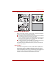
Operating Basics 8. Slide the Ultra Slim Bay latch to the unlock position. 9. Grasp the optical disc drive and slide it out. The optical disc drive and other Ultra Slim Bay modules can become hot with use. Be careful when removing the module. Lock screw (Unlock position) Lock position Optical disc drive Ultra Slim Bay latch Figure 4-19 Removing the optical disc drive Inserting a module To insert the Ultra Slim Bay HDD Adaptor, follow the steps as described below: 1.
Operating Basics Ultra Slim Bay Case (UJ-862 model only) The DVD Super Multi drive (UJ-862) is equipped with an Ultra Slim Bay Case. This section explains how to remove and install the DVD Super Multi drive unit (UJ-862). Store the DVD Super Multi drive unit (UJ-862 model only) in the Ultra Slim Bay Case when removing it from the computer or transporting it. Refer to Ultra Slim Bay Case (UJ-862 model only) section in this chapter.
Operating Basics Using optical disc drives The full-size drive provides high-performance execution of CD/DVD-ROMbased programs. You can run either 12 cm (4.72") or 8 cm (3.15") CD/DVDs without an adaptor. An ATAPI interface controller is used for CD/DVD-ROM operation. When the computer is accessing a CD/DVDROM, an indicator on the drive glows. Use the WinDVD application to view DVD-Video discs.
Operating Basics 3. Lay the CD/DVD, label side up, in the disc tray. Laser lens Figure 4-24 Inserting a CD/DVD When the disc tray is fully opened, the edge of the computer will extend slightly over the CD/DVD tray. Therefore, you will need to turn the CD/DVD at an angle when you place it in the disc tray. After seating the CD/DVD, however, make sure it lies flat. ■ Do not touch the laser lens or any portion of its surrounding casing as this could cause misalignment.
Operating Basics 5. Push the center of the disc tray to close it. Press gently until it locks into place. If the CD/DVD is not seated properly when the disc tray is closed, the CD/DVD might be damaged. Also, the disc tray might not open fully when you press the eject button. Figure 4-25 Closing the CD/DVD disc tray Removing discs To remove the CD/DVD, follow the steps as detailed below: Do not press the eject button while the computer is accessing the media drive.
Operating Basics 3. Push the center of the disc tray to close it. Press gently until it locks into place. Optical Drive Auto Lock This function automatically locks the optical disc drive eject button if the computer detects any vibration or other shocks while running on the battery. This function prevents the disc tray from opening even if the eject button is pushed unexpectedly.
Operating Basics How to remove CD/DVD when the disc tray will not open Pressing the eject button will not open the disc tray when the computer power is off. If the power is off, you can open the disc tray by inserting a slender object (about 15 mm) such as a straightened paper clip into the eject hole near the eject button. Eject hole Figure 4-27 Manual release with the eject hole Turn off the power before you use the eject hole.
Operating Basics When writing information to media using an optical drive, you should always ensure that you connect the AC adaptor to a live power socket. It is possible that, if data is written while powered by the battery pack, the write process may sometimes fail due to low battery power - in these instances data loss may occur.
Operating Basics CD-RW: (Multi-Speed and High-Speed) MITSUBISHI CHEMICAL CORPORATION RICOH Co., Ltd. CD-RW: (Ultra-Speed) MITSUBISHI CHEMICAL CORPORATION DVD-R: DVD Specifications for Recordable Disc for General Version 2.0 TAIYO YUDEN CO., LTD. Matsushita Electric Industrial Co., Ltd DVD-R (Dual Layer): MITSUBISHI CHEMICAL CORPORATION DVD+R: MITSUBISHI CHEMICAL CORPORATION RICOH Co., Ltd. DVD+R (Double Layer): MITSUBISHI CHEMICAL CORPORATION DVD-RW: DVD Specifications for Recordable Disc for Version 1.
Operating Basics ■ DVD Super Multi drive cannot use discs that allow writing faster than 16x speed (DVD-R and DVD+R media), 8x speed (DVD-R (Dual Layer), DVD+RW and DVD+R (Double Layer) media), 6x speed (DVDRW media), 5x speed (DVD-RAM media). ■ Some types and formats of DVD-R (Dual Layer) and DVD+R (Double Layer) discs may be unreadable. ■ 2.6GB and 5.2GB DVD-RAM media cannot be read from or written to. ■ DISC created in DVD-R (Dual Layer) format4 (Layer Jump Recording) cannot be read.
Operating Basics ■ Before you enter either Sleep Mode or Hibernation Mode, take care to ensure that any DVD-RAM writing has been completed. In this instance, writing is finished if you can eject the DVD-RAM media. ■ Be sure to close all other software programs except for the writing software itself. ■ Do not run software such as a screen saver which can put a heavy load on the processor. ■ Operate the computer at its full power settings - do not use any powersaving features.
Operating Basics ■ Make sure that the write/rewrite operation is completed before going into either Sleep Mode or Hibernation Mode (writing is completed if you can remove an optical media on the DVD Super Multi drive). ■ If the media is of poor quality, or is dirty or damaged, writing or rewriting errors may occur. ■ Set the computer on a level surface and avoid places subject to vibration such as airplanes, trains or cars. In addition, do not use the computer on an unstable surface such as a stand.
Operating Basics ■ TOSHIBA Disc Creator does not support recording to DVD-RAM discs to achieve this you should use Windows Explorer or another similar utility. ■ When you back up a DVD disc, be sure that the source drive supports recording to DVD-R, DVD-R (Dual Layer), DVD-RW, DVD+R, DVD+R (Double Layer) or DVD+RW media - if this is not the case then the source disc might not be backed up correctly.
Operating Basics Media care This section provides tips on protecting data stored on your CD's, DVD's and floppy diskettes. Handle your media with care. Following the simple precautions listed below will increase the lifetime of your media and protect the data stored on it. CD/DVDs 1. Store your CD's and DVD's in the containers they originally came in to protect them and keep them clean. 2. Do not bend the CD's or DVD's. 3.
Operating Basics 8. Data may be lost if the floppy diskette is twisted, bent, or exposed to direct sunlight, extreme heat or cold. 9. Do not place heavy objects on your floppy diskettes. 10. Do not eat, smoke, or use items such as erasers near your floppy diskettes as foreign particles inside the jacket of the floppy diskette can damage the magnetic surface. 11. Magnetic energy can destroy the data on your floppy diskettes.
Operating Basics Audio Enhancements In order to apply the sound effects for your current speaker, follow the steps below. 1. Right click on the speaker icon on the Taskbar, and select Playback Devices from the sub menu. 2. Select Speakers, and click Properties. 3. On the Enhancements tab select the sound effects you would like, and click Apply. Realtek HD Audio Manager You can confirm and change the audio configuration using the Realtek Audio Manager.
Operating Basics TOSHIBA Mic Effect TOSHIBA Mic Effect provides you with a hands-free environment for holding mutual communication via the Internet Protocol or Local Area Network. If you wish to communicate with someone on your computer, you can use a messenger application. However, with such an application, you would hear your own voice returning to you as echo during the communication if you did not use a headset system or headphone. TOSHIBA Mic Effect will reduce these echoes generated on your computer.
Operating Basics Region selection Telecommunication regulations vary from one region to another, so you will need to make sure the internal modem’s settings are correct for the region in which it will be used. The built-in modem can be used only in specified countries and regions. Using the modem in an area not specified for use may cause a system failure. Check the specified areas carefully before using it. To select a region, follow the steps as detailed below: 1.
Operating Basics Location list for region selection. Displays a sub-menu appears which details location information. Open dialog box, if the modem and Telephony Current Location region code do not match. Displays a warning if the current settings for both region code and telephony location are different. Modem Selection If the computer cannot recognize the internal modem, a dialog box is displayed from which you should select the appropriate communications port for your modem to use.
Operating Basics 2. Plug the other end of the modular cable into a telephone jack. Telephone jack Modem jack Figure 4-28 Connecting the internal modem Do not pull on the cable or move the computer while the cable is connected. If you use a storage device such as an optical drive or hard disk drive connected to a 16-bit PC Card, you might experience the following problems with the operation of the modem: ■ The modem speed is slow or communication is periodically interrupted.
Operating Basics Wireless communications The computer’s wireless communication function supports both Wireless LAN and Bluetooth devices. Only some models are equipped with both Wireless LAN and Bluetooth functions. ■ Do not use the Wireless LAN (Wi-Fi), Bluetooth or Wireless WAN functionalities near a microwave oven or in areas subject to radio interference or magnetic fields. Interference from a microwave oven or other source can disrupt Wi-Fi, Bluetooth or Wireless WAN operation.
Operating Basics ■ Wired Equivalent Privacy (WEP) data encryption based on an 128-bit encryption algorithm ■ Wi-Fi Protected Access (WPA) The transmission speed over the wireless LAN, and the distance over which the wireless LAN can reach, may vary depending on surrounding electromagnetic environment, obstacles, access point design and configuration, client design and software/hardware configurations.
Operating Basics Radio links You can easily establish links between two or more devices, with these links being maintained even if the devices are not within a line-of-sight of each other. Security Two advanced security mechanisms ensure a high level of security: ■ Authentication prevents access to critical data and makes it impossible to falsify the origin of a message. ■ Encryption prevents eavesdropping and maintains link privacy.
Operating Basics Wireless communication Indicator The wireless communication indicator shows the status of the computer's wireless communication functions. Indicator status Indication Indicator off The wireless communication switch is off - no wireless functionality is available. Indicator glows Wireless communication switch is on. Wireless LAN or Bluetooth is turned on by an application.
Operating Basics Connecting the LAN cable To connect the LAN cable, follow the steps as detailed below: ■ Connect the AC adaptor before connecting the LAN cable. The AC adaptor must remain connected during LAN use. If you disconnect the AC Adaptor while the computer is accessing a LAN, the system may hang up. ■ Do not connect any other cable to the LAN jack except the LAN cable. Otherwise, malfunctions or damage may occur.
Operating Basics Disconnecting the LAN cable To disconnect the LAN cable, follow the steps as detailed below: Make sure the LAN Active indicator (orange LED) is out before you disconnect the computer from the LAN. 1. Pinch the lever on the connector in the computer’s LAN jack and pull out the connector. 2. Disconnect the cable from the LAN hub or router in the same manner. Check with your LAN administrator and hardware or software vendor before disconnecting from the hub.
Operating Basics ■ Disconnect the AC adaptor and all peripherals before moving the computer. ■ Close the display panel. Always make sure the display panel is closed in Laptop mode before turning the computer upside down. ■ Do not pick up the computer by its display panel. ■ Before carrying your computer, shut it down, disconnect the AC adaptor and allow it to cool down - a failure to follow this instruction may result in minor heat injury.
Operating Basics Taskbar icon State Icon Description Normal TOSHIBA HDD Protection is enabled. Protection TOSHIBA HDD Protection is active. The hard disk drive head is in a safe position. OFF TOSHIBA HDD Protection is disabled. TOSHIBA HDD Protection Properties You can change the TOSHIBA HDD Protection settings by using the TOSHIBA HDD Protection Properties window. To open the window, click Start -> All Programs -> TOSHIBA -> Utilities -> HDD Protection Settings.
Operating Basics ■ This 3D object virtually represents the Computer's internal Hard Disk Drive. This representation may vary from the actual number of disks, disk rotation, head movement, part size, shape and direction. ■ This feature may use a large amount of CPU and memory on some models. The computer may become slow or sluggish when attempting to run other applications while the 3D Viewer is displayed.
Chapter 5 The Keyboard The computer's keyboard layouts are compatible with a 104/105-key enhanced keyboard - by pressing some keys in combination, all of the 104/105-key enhanced keyboard functions can be performed on the computer. The number of keys available on your keyboard will depend on which country/region your computer is configured for, with keyboards being available for numerous languages.
The Keyboard Function keys: F1 … F12 The function keys (not to be confused with the special FN key) are the twelve keys at the top of your keyboard - these keys function differently from other keys. F1 through F12 are called function keys because they execute programmed functions when pressed and, when used in combination with the FN key, those keys marked with icons also execute specific functions on the computer.
The Keyboard Press FN + F10 or FN + F11 to access the computer's integrated keypad. When activated, the keys with grey markings on their bottom edge become either numeric keypad keys (FN + F11) or cursor control keys (FN + F10). Please refer to the Keypad overlay section in this chapter for more information on how to operate these keys, taking care to note that the power on default for both settings is off. Press FN + F12 (ScrLock) to lock the cursor on a specific line. The power on default is off.
The Keyboard Sleep: Pressing FN + F3 switches the system to Sleep Mode. Hibernate: Pressing FN + F4 switches the system to Hibernation Mode. Output: Pressing FN + F5 changes the active display device. Brightness Down: Pressing FN + F6 decreases the computer's display panel brightness in individual steps. Brightness Up: Pressing FN + F7 increases the computer's display panel brightness in individual steps.
The Keyboard ODD: Pressing FN + Tab turns the power of the optical disc drive on/off or ejects the disc tray. TOSHIBA Zooming Utility (reduce): Pressing FN + 1 reduces the icon size on the desktop or the font sizes within one of the supported application windows. TOSHIBA Zooming Utility (enlarge): Pressing FN + 2 enlarges the icon size on the desktop or the font sizes within one of the supported application windows.
The Keyboard Keypad overlay Your computer's keyboard does not have a separate numeric keypad but includes a numeric keypad overlay which functions like one - this is located in the center of the keyboard with the relevant keys having grey letters at their front edge. The overlay provides the same functions as the numeric keypad on a standard 104/105-key enhanced keyboard. Turning on the overlays The numeric keypad overlay can be used for numeric data input or cursor and page control.
The Keyboard Temporarily using normal keyboard (overlay on) While using the overlay, you can temporarily access the normal keyboard functions without having to turn the overlay off: 1. Hold down FN key and press any other key - this key will operate as if the overlay were off. 2. Type upper-case characters by holding down FN + SHIFT and pressing a character key. 3. Release FN key to continue using the selected overlay function.
Chapter 6 Power and Power-Up Modes The computer's power resources include the AC adaptor, battery pack and any internal batteries. This chapter provides details on making the most effective use of these resources, and includes information on charging and changing batteries, tips for saving battery power, and information on the different power-up modes.
Power and Power-Up Modes Table 6-1 Power conditions continued AC adaptor connected AC adaptor not connected User’s Manual Power on Power off (no operation) 2nd battery fully charged • Operates • No charge • LED: 2nd battery green DC IN green • No charge • LED: 2nd battery green DC IN green 2nd battery partially charged or no charge • Operates • Quick charge*2 2 • LED: 2nd battery orange • Charge* • LED: 2nd battery orange DC IN green DC IN green No 2nd battery installed • Operates • No charge •
Power and Power-Up Modes Table 6-1 Power conditions continued Power on AC adaptor not connected 2nd battery charge is above low battery trigger point • Operates • LED: 2nd battery off DC IN off 2nd battery charge is below low battery trigger point • Operates • LED: 2nd battery flashes orange DC IN off 2nd battery charge is exhausted Computer shuts down *3 No 2nd battery is installed • No operation *5 • LED: 2nd battery off DC IN off Power off (no operation) 1 When the Slice Expansion Battery is n
Power and Power-Up Modes Monitoring of power condition As shown in the below table, the Battery, 2nd battery, DC IN and Power indicators on the system indicator alert you to the computer’s operating capability and battery charge status. Battery indicator Check the Battery indicator to determine the status of the main battery and the 2nd battery indicator to determine the status of the Slice Expansion Battery.
Power and Power-Up Modes Power indicator Check the Power indicator to determine the power status of the computer the following indicator conditions should be noted: Green Indicates power is being supplied to the computer and the computer is turned on. Blinking orange Indicates that the computer is in Sleep Mode and that there is sufficient power available (AC adaptor or battery) to maintain this condition. In Sleep Mode, this indicator will turn on for one second and off for two seconds.
Power and Power-Up Modes Real Time Clock (RTC) battery The Real Time Clock (RTC) battery provides power for the internal real time clock and calendar function and also maintains the system configuration while the computer is turned off.
Power and Power-Up Modes ■ Never remove the battery pack while the Wake-up on LAN function is enabled. Data will be lost. Before you remove a battery pack, disable the Wake-up on LAN function. ■ Never remove the battery pack while the Wake-up on Wireless LAN function is enabled. Data will be lost. Before you remove a battery pack, disable the Wake-up on Wireless LAN function.
Power and Power-Up Modes Battery charging notice The battery may not begin charging immediately under the following conditions: ■ The battery is extremely hot or cold (if the battery is extremely hot, it might not charge at all). To ensure the battery charges to its full capacity, you should charge it at room temperature of between 5° to 35°C (41° to 95°F). ■ The battery is nearly completely discharged.
Power and Power-Up Modes Maximizing battery operating time A battery's usefulness depends on how long it can supply power on a single charge, while how long the charge lasts in a battery depends on: ■ Processor speed ■ Screen brightness ■ System Sleep Mode ■ System Hibernation Mode ■ Display power off period ■ Hard disk drive power off period ■ How often and for how long you use the hard disk drive and external disk(c) drives, for example, optical disc and floppy diskette drive.
Power and Power-Up Modes Extending battery life To maximize the life of your battery packs: ■ At least once a month, disconnect the computer from a power source and operate it on battery power until the battery pack fully discharges. Before doing so, follow the steps as detailed below. 1. Turn off the computer's power. 2. Disconnect the AC adaptor and turn on the computer's power - if it does not turn on then go to Step 4. 3. Operate the computer on battery power for five minutes.
Power and Power-Up Modes Removing the battery pack To remove a discharged battery, follow the steps as detailed below: 1. Save your work. 2. Turn the computer's power off - ensure that the Power indicator is off. 3. Remove all cables and peripherals that are connected to the computer. 4. Close the display panel and turn the computer upside down. Always make sure the display panel is closed in Laptop mode before turning the computer upside down. 5.
Power and Power-Up Modes Installing the battery pack To install a battery pack, follow the steps as detailed below: Do not touch the battery release latch while holding the computer or the battery pack might fall out due to the unintentional release of the battery release latch and cause injuries. 1. Insert the battery pack as far as it will go into the computer (1). 2. Ensure that the battery pack is securely in place and the battery lock (2) is in its ( ) position.
Power and Power-Up Modes 3. Remove the protective cap from the Slice Expansion Battery. 4. Open latches on the Slice Expansion Battery and fit a tab on the battery into the docking port on the underside of the computer. Latches Tab Tab Tab Docking port Figure 6-4 Seating the Slice Expansion Battery 5. Close the latches to secure the Slice Expansion Battery to the computer.
Power and Power-Up Modes 5. Open the release latches in the direction of the arrows. Latches Figure 6-6 Releasing the latches 6. Lift off the Slice Expansion Battery. Figure 6-7 Removing the Slice Expansion Battery 7. Be sure to replace the protective cap before storing the Slice Expansion Battery. TOSHIBA Password Utility The TOSHIBA Password Utility provides two levels of password security: User and Supervisor.
Power and Power-Up Modes User Password To start the utility, point to or click the following items: Start -> All Programs -> TOSHIBA -> Utilities ->Password Utility The User Password dialog box contains two main fields: User Password and User Token. User authentication may be required to validate user rights when using "TOSHIBA Password Utility" to delete or change passwords, or create tokens, etc. User Password field ■ Set (button) Click this button to register a password of up to 50 characters.
Power and Power-Up Modes ■ If you forget your HDD User Password, TOSHIBA will NOT be able to assist you, and your HDD will be rendered COMPLETELY and PERMANENTLY INOPERABLE. TOSHIBA will NOT be held responsible for any loss of any data, any loss of use or access to your HDD, or for any other losses to you or any other person or organization that result from the loss of access to your HDD. If you can’t accept this risk, don’t register the HDD User Password.
Power and Power-Up Modes Supervisor Password If you set a Supervisor Password, some functions might be restricted when a user logs on with the User Password. To set a Supervisor Password, execute the file TOSPU.EXE. The file is located at: C:\Program Files\Toshiba\PasswordUtility\TOSPU.exe This utility lets you do the following: ■ Register, delete or change the Supervisor Password. ■ Create or invalidate a Supervisor Password token.
Power and Power-Up Modes Tablet mode Enter your password by tapping the on-screen keyboard using the Tablet PC Pen or your finger. On-screen keyboard can not be used in Display screen model. Figure 6-8 On-screen keyboard ■ The beep sounds when tapping the on-screen keyboard with the Tablet PC Pen or your finger. An * (asterisk) is displayed after "Password =" and one character is input for every tapping. Register your password to the computer in the Laptop mode using the standard keyboard.
Power and Power-Up Modes Hot keys You can use the FN + F3 hot key to enter Sleep Mode or FN + F4 to enter Hibernation Mode - please refer to Chapter 5, The Keyboard for further details. Panel power on/off You can set up your computer so that power is turned off automatically when you close the display panel, and turned on again when you open it. Please note that this function is only available for Sleep Mode or Hibernation Mode, not for Boot Mode.
Chapter 7 HW Setup & BIOS Setup This chapter explains how to use the TOSHIBA HW Setup program to configure your computer, and provides information on settings for various functions. Accessing HW Setup To run the HW Setup program, click Start -> All Programs -> TOSHIBA -> Utilities -> HWSetup. HW Setup window The HW Setup window contains a number of tabs (General, Display, Boot Priority, Keyboard, CPU, LAN, Device Config and USB) to allow specific functions of the computer to be configured.
HW Setup & BIOS Setup General This window displays the BIOS version and contains two buttons : Default and About. Default Return all HW Setup values to the factory settings. About Display the HW Setup version. Setup This field displays the installed BIOS version and date. Display This tab lets you customize your computer’s display settings for either the internal display or an external monitor. Power On Display This tab allows you to select the display to be used when the computer is started.
HW Setup & BIOS Setup Boot Priority Boot Priority Options This tab allows you to select the priority for booting the computer - the following settings are available: FDD ! HDD ! CDROM ! LAN The computer looks for bootable files on devices in the following order: 1. floppy diskette drive*1, 2. hard disk drive, 3. CD-ROM*2, 4. LAN. HDD ! FDD ! CDROM ! LAN The computer looks for bootable files on devices in the following order: 1. hard disk drive, 2. floppy diskette drive*1, 3. CD-ROM*2, 4. LAN.
HW Setup & BIOS Setup To change the boot drive, follow the steps below. 1. Hold down F12 and boot the computer. 2. The following menu will be displayed with the following icons: Built-in hard disk drive, Ultra Slim Bay hard disk drive, CD-ROM, FDD (or SD memory card), Network (LAN), USB Memory boot. Please note that a highlighted bar will only appear under the selected device. 3. Use the left/right cursor keys to highlight the boot device you want and press ENTER.
HW Setup & BIOS Setup ■ If a boot command is not found on the first detected hard disk drive, the system will not boot from next hard disk drive in the list, instead it will search for the next device in the Boot Priority list and startup from this as appropriate. ■ Please be aware that some modules may not be displayed. USB Memory BIOS Support Type This option allows you to set the type of the USB memory to be used as a startup device.
HW Setup & BIOS Setup CPU This function allows you to set the processor's operating mode. Dynamic CPU Frequency Mode This option allows you to configure the power saving modes associated with the processor - the following settings are available: Dynamically Switchable The processor's power consumption and automatic clock speed switching functions are enabled - in use the processor's operation is automatically switched when necessary (default).
HW Setup & BIOS Setup Built-in LAN This feature enables or disables the Built-in LAN. Enabled Enables Built-in LAN functions (Default). Disabled Disables Built-in LAN functions. Device Config Device Configuration This option allows you to set how the computer's hardware devices will be configured. All Devices The computer's BIOS will setup and configure all devices. Setup by OS The operating system will setup and configure all of the devices that it can control (default).
HW Setup & BIOS Setup BIOS Setup Program Settings for some features are carried out in the BIOS setup program. Notes Before Using the BIOS Setup Application ■ In most cases, changes to the system's configuration should be made within Windows by using applications such as TOSHIBA HW Setup, TOSHIBA Password Utility, Windows Device Manager and so forth.
HW Setup & BIOS Setup Ending the BIOS Setup Program Halfway The configuration settings can be terminated halfway without saving any of the changes made by following the steps detailed below: 1. Press the ESC key - the Exit without saving? (Y/N) prompt to be displayed at the bottom of the screen. 2. Press the Y key - the BIOS setup application will exit and the computer will automatically restart.
HW Setup & BIOS Setup Virtualization Technology Virtualization Technology sets enable or disable of the Intel® Virtualization Technology installed in the CPU. Intel® Virtualization Technology is the technique that allows one machine to operate as multiple virtual machines. The Virtualization Technology is supported with some models. The Disabled command does not allow use of the Intel® Virtualization Technology. The Enabled command allows use of the Intel® Virtualization Technology.
HW Setup & BIOS Setup Auto Power On This is a function for automatically turning on the computer. This item shows the current Auto Power On setting. When Alarm Time, Wake-up on LAN, or Critical Battery Wake-up are Enabled, Auto Power On is also Enabled. Alarm Time, Wake-up on LAN, on Battery and Critical Battery Wake-up can be configured under OPTIONS. Enabled Either Alarm Time, Wake-up on LAN, or Critical Battery Wake-up is set to Enabled (Default).
HW Setup & BIOS Setup Security controller Please note that the security controller settings are available on the second page of the BIOS setup application. TPM This setting enables or disables the computer's Trusted Platform Module (TPM) security controller. The Trusted Platform Module security controller is supported with some models. Enabled Enable Trusted Platform Module security. Disabled Disable Trusted Platform Module security (default).
HW Setup & BIOS Setup SATA Controller Mode This feature sets the SATA Controller Mode. The SATA Controller Mode is supported with some models. AHCI Sets AHCI which is the mode for Windows Vista® (Default). Compatibility Sets the mode for legacy OS. Use this mode when the driver corresponding to AHCI is not used. USB Sleep and Charge function This section describes the settings for "USB Sleep and Charge function".
Chapter 8 Troubleshooting TOSHIBA have designed this computer for durability, however, should problems occur you are able to use the procedures detailed in this chapter to help determine the cause. All users should become familiar with this chapter as knowing what might go wrong can help prevent problems from occurring in the first place.
Troubleshooting Preliminary checklist You should always consider the simplest solution first - the items detailed in this checklist are easy to fix and yet can cause what appears to be a serious problem: ■ Make sure you turn on all peripheral devices before you turn on the computer - this includes your printer and any other external device you are using.
Troubleshooting ■ Do you hear any beeps, if so how many, are they long or short and are they high pitched or low pitched? In addition, is the computer making any unusual noises? Write down what you hear. Record your observations so you can describe them in detail to your reseller, dealer or service provider. Software Hardware The problems may be caused by your software or disk.
Troubleshooting System start-up When the computer does not start properly, check the following items: ■ Self Test ■ Power Sources ■ Power-on Password Self test While booting up the computer, self test is executed automatically and the TOSHIBA logo is displayed on the screen. This message remains on the screen for a few seconds. If the self test is successful, the computer tries to load the operating system according to how the Boot Priority option is set within the TOSHIBA HW Setup program.
Troubleshooting It is recommended to leave the computer off until the interior reaches room temperature even though the DC IN indicator stops blinking. If the computer has reached room temperature and it still does not start, or if it starts but shuts down quickly, contact your reseller, dealer or service provider. Computer shuts down and its DC IN indicator is flashing green This indicates a problem with the heat dispersal system - you should contact your reseller, dealer or service provider.
Troubleshooting Problem Procedure Battery doesn’t charge when the AC adaptor is attached (Battery indicator does not glow orange). If the battery is completely discharged, it will not begin charging immediately, in these instances you should wait a few minutes before trying again. If the battery still does not charge, you should check that the power outlet the AC adaptor is connected to is supplying power - this can be tested by plugging another appliance into it.
Troubleshooting Real Time Clock Problem Procedure The following message is Displayed on the screen: RTC battery is low or CMOS checksum is inconsistent. Press [F1] key to set Date/Time. The charge in the Real Time Clock (RTC) battery has run out - you will need to set the date and time in the BIOS setup application by using the following steps: 1. Press the F1 key - the BIOS setup application will load. 2. Set the date in the System Date field. 3. Set the time in the System Time field. 4.
Troubleshooting Internal display panel Apparent computer's display panel problems may be related to the computer's setup and configuration - please refer to Chapter 7, HW Setup & BIOS Setup, for further information. Problem Procedure No display Press the FN + F5 hot keys to adjust the display priority, and to make sure it is not set for output to an external monitor. Markings appear on the These marks may have come from contact with the keyboard and Touch Pad while the display computer's display panel.
Troubleshooting Problem Procedure Slow performance The files on the hard disk drive may be fragmented - in this instance you should run the disk Defragmentation utility to check the condition of your files and the hard disk drive. Please refer to the operating system's documentation or online Help File for further information on operating and using the Defragmentation utility. As a last resort you should reformat the hard disk drive and then reload the operating system and all other files and data.
Troubleshooting Check the type of CD/DVD you are using. The drive supports: DVD-ROM: DVD-ROM, DVD-Video CD-ROM: CD-DA, CD-Text, Photo CDTM (single/multi-session), CD-ROM Mode 1, Mode 2, CD-ROM XA Mode 2 (Form1, Form2), Enhanced CD (CD-EXTRA), Addressing Method 2 Recordable DVD: DVD-R/-R DL, DVD+R/+R DL, DVD-RW, DVD+RW, DVD-RAM Check the region code on the DVD. It must match that on the DVD Super Multi drive. Region codes are listed in the Optical disc drives section in Chapter 2, The Grand Tour.
Troubleshooting PC Card For further information, please refer to Chapter 3, Hardware, Utilities and Options. Problem Procedure PC Card error occurs Remove the PC Card from the computer and then reinsert it in order to ensure it is firmly connected. In the event that the PC Card is attached to an external peripheral device, ensure that this connection is properly made. If the problem persists, then you should refer to the documentation supplied with your PC Card for further information.
Troubleshooting Problem Procedure You cannot read a file Check to ensure the required file is actually on the SD/SDHC Card that is inserted into the computer. If you are still unable to resolve the problem, contact your reseller, dealer or service provider. Memory Stick For further information, please refer to Chapter 3, Hardware, Utilities and Options.
Troubleshooting Problem Procedure You cannot read a file Check to ensure the required file is actually on the xD picture card that is inserted into the computer. If you are still unable to resolve the problem, contact your reseller, dealer or service provider. MultiMediaCard For further information, please refer to Chapter 3, Hardware, Utilities and Options.
Troubleshooting User’s Manual Problem Procedure Double-tapping does not work In this instance, you should initially try changing the double-click speed setting within the Mouse Control utility. 1. To access this utility, click Start -> Control Panel -> Hardware and Sound -> Mouse icon. 2. Within the Mouse Properties window, click the Buttons tab. 3. Set the double-click speed as required and click OK.
Troubleshooting USB mouse Problem Procedure On-screen pointer does In this instance the system might be busy - Try not respond to mouse moving the mouse again after waiting a short operation while. Remove the mouse from the computer and then reconnect it to a free USB port it in order to ensure it is firmly attached. User’s Manual Double-clicking does not work In this instance, you should initially try changing the double-click speed setting within the Mouse Control utility. 1.
Troubleshooting Fingerprint Sensor User’s Manual Problem Procedure Reading of the fingerprint was not successful. In this instance you should try the fingerprint reading operation again using the correct finger position - please refer to Using the Fingerprint Sensor in Chapter 4, Operating Basics for further information. Alternatively, you should try the recognition process again using another enrolled finger. The fingerprint sensor compares and analyzes the unique characteristics in a fingerprint.
Troubleshooting USB device In addition to the information in this section, please also refer to the documentation supplied with your USB device. Problem Procedure USB device does not work Remove the USB device from the computer and then reconnect it to a free port it in order to ensure it is firmly attached. Ensure that any required USB device drivers are properly installed - to achieve this you should refer to both the device documentation and the operating system documentation.
Troubleshooting Problem Procedure Some external devices may not be able to use the "USB Sleep and Charge function". In this case, please try one or more of the following methods. ■ Change a mode setting of [Enabled] by the BIOS Setup. ■ Turn OFF the computer while external devices are connected. ■ Connect external devices after turning OFF of the computer. If this function can not be still used, change the setting to [Disabled] in the BIOS Setup and stop using this function.
Troubleshooting Problem Procedure The "USB WakeUp When "USB Sleep and Charge function" is set to function" does not work. [Enabled] in the BIOS Setup, the "USB WakeUp function" does not work for ports that support the USB Sleep and Charge function. In that case, use an USB port that does not have the USB Sleep and Charge function-compatible icon ( ) or change the "USB Sleep and Charge function" setting to [Disabled] in the BIOS Setup.
Troubleshooting Sound system In addition to the information in this section, please also refer to the documentation supplied with your audio device. Problem Procedure No sound is heard Adjust the volume control dial. Check the software volume settings. Please check to see if Mute is turned to Off Check to make sure the headphone connection is secure. Check within the Windows Device Manager application to ensure the sound device is enabled and that the device is properly working.
Troubleshooting External monitor Please also refer to Chapter 3, Hardware, Utilities and Options, and to the documentation supplied with your monitor for further information. Problem Procedure Monitor does not turn on After confirming that the monitor's power switch is on, you should check the connections to make sure that the power cord/adaptor is firmly connected to the monitor and to a working power outlet. No display Try adjusting the contrast and brightness controls on the external monitor.
Troubleshooting i.LINK (IEEE1394) device Problem Procedure i.LINK device does not function Make sure the cable is securely connected to the computer and to the device. Make sure the device’s power is turned on. Reinstall the drivers. Open the Windows Control Panel and double-click the Add Hardware icon. Follow the on-screen directions. Restart Windows. If problems persist, contact your dealer. Modem For additional information, please also refer to Appendix C, AT Commands and Appendix D, S-registers.
Troubleshooting Problem Procedure Communication is cut off unexpectedly The computer will automatically cut off communication when connection with the carrier is not successful for a set time interval - try lengthening this time interval within your communication application. A CONNECT display is quickly replaced by NO CARRIER Ensure that the communication application's error control feature is set correctly. You are also able to use the AT\N command please refer to Appendix C, AT Commands for further
Troubleshooting Wireless LAN If the following procedures do not restore LAN access, consult your LAN administrator. For more information on wireless communication, refer to Chapter 4, Operating Basics. Problem Procedure Cannot access Wireless LAN Make sure the computer's Wireless communication switch is set to on. If problems persist, contact your LAN administrator. Bluetooth For further information on Bluetooth wireless communication, please refer to Chapter 4, Operating Basics.
Troubleshooting Recovery Discs Problem Procedure The following message appears when executing Recovery Disc Creator. "The Recovery Disc Creator can not be launched because there is no recovery partition." You will see this message if you have previously chosen to remove the partition and are trying to create "Recovery Media". When there is no recovery partition, the Recovery Disc Creator cannot make Recovery Media.
Troubleshooting ■ Use a proven specialized utility to overwrite all data ■ Take the hard disk drive to a professional deletion service All data deletion costs will be borne by you. TOSHIBA support If you require any additional help using your computer or if you are having problems operating the computer, you may need to contact TOSHIBA for additional technical assistance.
Troubleshooting Outside of Europe In Europe Singapore TOSHIBA Singapore Pte. Ltd. 438B Alexandra Road #06-01 Alexandra Technopark Singapore 119968 Spain TOSHIBA Information Systems, ESPAÑA Parque Empresarial San Fernando Edificio Europa, la Planta, Escalera A 28830 Madrid United States of America TOSHIBA America Information Systems, Inc. 9740 Irvine Boulevard Irvine, California 92618 USA United Kingdom TOSHIBA Information Systems (U.K.) Ltd.
Appendix A Specifications This appendix summarizes the computer’s technical specifications. Physical Dimensions This section summarizes the computer’s technical specifications. Physical Dimensions Weight (typical)* 2.0 kilograms, configured with: 12.1"WXGA, 1,024 MB RAM, 80GB HDD, DVD Super Multi drive, LAN (1000M bps), Wireless LAN, modem, Tablet PC Pen. *Digitizer screen model equipped with UJ-862. Weight will vary with other configurations. Above weight is measured at specific criteria.
Specifications Wet-bulb temperature 26°C maximum Conditions Altitude (from sea level) Operating -60 to 3,000 meters Non-operating -60 to 10,000 meters maximum Power Requirements AC adaptor 100-240 volts AC 50 or 60 hertz (cycles per second) Computer 15 V DC 5.0 amperes Built-in Modem This information is applicable to the models equipped with a built-in modem.
Specifications User’s Manual Communication speed Data transmission and reception 300/1200/2400/4800/7200/9600/12000/14400/16 800/19200/21600/24000/26400/28800/31200/33 600 bps Data reception only with V.
Appendix B Display Controller and Video mode Display controller The display controller interprets software commands into hardware commands that turn particular parts on the screen on or off. Due to the display panel's increased resolution, lines may appear broken in when displaying images in full-screen text mode. The display controller also controls the video mode and uses industry standard rules to govern the screen resolution and the maximum number of colors that can be displayed at any one time.
Appendix C AT Commands This information is applicable to the models equipped with a built-in modem. In most cases, you will not need to type AT commands manually. However, there might be some occasions when you will need to do so. This chapter describes AT commands for data mode. Fax and voice commands are taken care of by application software. The format for entering AT commands is: ATXn where X is the AT command, and n is the specific value for that command. After you type in the command press ENTER.
AT Commands A/ Repeat last command This command repeats the last command string entered. Do not precede this command with an AT prefix or conclude it by pressing ENTER. A Answer command This command instructs the modem to go off-hook and answer an incoming call. Bn Communication standard setting This command determines the communication standard CCITT or Bell. B0 Selects CCITT V.22 mode when the modem is at 1200 bps. B1 Selects Bell 212A when the modem is at 1200 bps (default). B15 Selects V.
AT Commands En Echo command This command controls whether or not the characters entered from your computer keyboard are displayed on your monitor (echoed) while the modem is in command mode. E0 Disables echo to the computer. E1 Enables echo to the computer (default). Result Codes: OK n=0,1 ERROR Otherwise Hn Hook control This command instructs the modem to go on-hook to disconnect a call, or off-hook to make the phone line busy. H0 Modem goes on-hook (default). H1 Modem goes off-hook.
AT Commands M2 M3 The speaker is always on when modem is off-hook. Speaker is on until the carrier is detected, except when dialing. Result Codes: OK n=0,1,2,3 ERROR Otherwise Nn Modulation handshake This command controls whether or not the local modem performs a negotiated handshake at connection time with the remote modem when the communication speed of the two modems is different.
AT Commands Q1 Disables modem from sending result codes to the computer. Result Codes: OK n=0,1 ERROR Otherwise T Select tone dialing This command instructs the modem to send DTMF tones while dialing. Dialed digits are tone dialed until a P command or dial modifier is received. This is the default setting. Vn DCE response format This command controls whether result codes (including call progress and negotiation progress messages) are displayed as words or their numeric equivalents.
AT Commands Dial tone detect Disabled: The modem dials a call regardless of whether it detects a dial tone. Enabled: The modem dials only upon detection of a dial tone, and disconnects the call if the dial tone is not detected within 10 seconds. Busy tone detect Disabled: The modem ignores any busy tones it receives. Enabled: The modem monitors for busy tones.
AT Commands &D2 If the DTR signal is not detected while in on-line data mode, the modem disconnects (default). &D3 Reset on the on-to-off DTR transition. Result Codes: OK n=0,1,2,3 ERROR Otherwise &F Load factory settings This command loads the configuration stored and programmed at the factory. This operation replaces all of the command options and the Sregister settings in the active configuration with factory values. &F Recall factory setting as active configuration. &Gn V.
AT Commands &Tn Self-test commands These tests can help to isolate problems if you experience periodic data loss or random errors. &T0 Abort. Stops any test in progress. &T1 Local analog loop. This test verifies modem operation, as well as the connection between the modem and computer. Any data entered at the local DTE is modulated, then demodulated, and returned to the local DTE. To work properly, the modem must be off-line.
AT Commands \N3 V.42, MNP, or buffered (default). The modem attempts to connect in V.42 error control mode. If this fails, it attempts to connect in MNP mode. If this fails, it connects in buffer mode and continues operation. This is also known as V.42/MNP auto reliable mode (same as &Q5). \N4 V.42 or disconnect. The modem attempts to connect in V.42 error control mode. If this fails, the modem disconnects. \N5 V.42. MNP or buffered (same as \N3). \N7 V.42. MNP or buffered (same as \N3).
Appendix D S-registers This information is applicable to the models equipped with a built-in modem. S-registers contain the settings that determine how a number of functions of the internal modem operate. For example, how many times to let the telephone ring before the modem answers and how long to wait before it hangs up if a connection fails. You can also customize certain AT commands such as the escape sequence and command line termination.
S-registers S0 Auto answer ring number This register determines the number of rings the modem will count before automatically answering a call. Enter 0 (zero) if you do not want the modem to automatically answer at all. When disabled, the modem can only answer with an ATA command. Range:0-255 Default:0 Units:rings S1 Ring counter This register is read only. The value of S1 is incremented with each ring. If no ring occurs over a six-second interval, this register is cleared.
S-registers S5 Command line editing character (user defined) This register sets the character recognized as a backspace and pertains to asynchronous only. The modem will not recognize the backspace character if it is set to a value that is greater than 32 ASCII. This character can be used to edit a command line. When the echo command is enabled, the modem echoes back to the local DTE the backspace character, an ASCII space character, and a second backspace character.
S-registers S8 Comma pause time This register sets the time, in seconds, that the modem must pause when it encounters a comma (,) in the dial command string. In some countries/regions, S8 will set both wait before dialing and comma pause time. Range:0-255 Default:2 Units:seconds S11 DTMF dialing speed This register determines the dialing speed which is prefixed for each country/region. Range:50-255 Default:95 Units:.
S-registers S37 = 10 12000 bps S37 = 11 14400 bps S37 = 12 16800 bps S37 = 13 19200 bps S37 = 14 21600 bps S37 = 15 24000 bps S37 = 16 26400 bps S37 = 17 28800 bps S37 = 18 31200 bps S37 = 19 33600 bps AT command set result codes The following table shows the result codes.
S-registers CONNECT 4800 EC* 1 11 Connection at 4800 bps *1 12 Connection at 9600 bps 1 EC* 13 Connection at 14400 bps *1 CONNECT 9600 EC CONNECT 14400 14 Connection at 19200 bps *1 24 Connection at 7200 bps 1 EC* 25 Connection at 12000 bps *1 86 Connection at 16800 bps CONNECT 19200 EC CONNECT 7200 EC CONNECT 12000 CONNECT 16800 EC CONNECT 300 1 EC* 40 Connection at 300 bps CONNECT 21600 EC *1 55 Connection at 21600 bps CONNECT 24000 EC *1 56 Connection at 24000 bps 1 E
Appendix E V.90 This information is applicable to the models equipped with a built-in modem. The TOSHIBA internal modem uses V.90 technology. The modem is capable of downstream speeds of 56kbps (kilobits per second) when connected to an Internet service provider that supports V.90. As with any modem, the actual throughput (speed of data transfer) depends on analog telephone line conditions, which can vary considerably.
V.90 Table E-1 Result codes for a V.90 connection User’s Manual No.
V.90 * EC stands for the Error Control method, which appears only when the extended result codes configuration option is enabled. EC is replaced by one of the following symbols, depending on the error control method used. V42bis V.42 error control and V.42bis data compression V42 V.42 error control only NoEC No error control protocol AT Command User’s Manual -V90=* V.90 Dial Line Rate -V90 sets the maximum V.90 downstream that the modem attempts to connect. -V90=0 V.90 disabled -V90=1 V.
Appendix F Wireless LAN This appendix is intended to help you get your Wireless LAN network up and running, with a minimum of parameters. Card Specifications Form Factor Compatibility Network Operating System Media Access Protocol User’s Manual PCI Express Mini Card ■ IEEE 802.11 Standard for Wireless LANS ■ Wi-Fi (Wireless Fidelity) certified by the Wi-Fi Alliance. The ‘Wi-Fi CERTIFIED’ logo is a certification mark of the Wi-Fi Alliance.
Wireless LAN Radio Characteristics Radio Characteristics of Wireless LAN Cards may vary according to: ■ Country/region where the product was purchased ■ Type of product Wireless communication is often subject to local radio regulations. Although Wireless LAN wireless networking products have been designed for operation in the license-free 2.4GHz and 5GHz band, local radio regulations may impose a number of limitations to the use of wireless communication equipment.
Wireless LAN Supported Frequency Sub-bands Subject to the radio regulations that apply in the countries/regions, your Wireless LAN card may support a different set of 5 GHz/2.4 GHz channels. Consult your Authorized Wireless LAN or TOSHIBA Sales office for information about the radio regulations that apply in the countries/regions. Wireless IEEE 802.11 Channels Sets (Revision B, G and n Draft 2.0) Frequency Range Channel ID 2400-2483.
Wireless LAN ■ In a Wireless LAN Access Point, the Wireless LAN card will use the factory-set default channel (printed in bold), unless the LAN Administrator selected a different channel when configuring the Wireless LAN Access Point device. Wireless IEEE 802.11 Channels Sets (Revision A and n Draft 2.
Wireless LAN 161 5805*2 165 5825*2 *1 Factory-set default channels *2 Refer to the sheet Approved Countries/Regions for use for the countries/regions that in which these channels can be used. When installing Wireless LAN cards, the channel configuration is managed as follows: ■ For wireless clients that operate in a Wireless LAN Infrastructure, the Wireless LAN card will automatically start operation at the channel identified by the Wireless LAN Access Point.
Appendix G Intel® Matrix Storage Manager If you are installing the operating system on a computer system which is configured for AHCI mode, you must pre-install the Intel® Matrix Storage Manager driver using the F6 installation method described in the Manually Setting up Windows (Windows Vista®) or Manually Setting up Windows Manually (Windows XP) sections. This model does not support RAID functionality.
Intel® Matrix Storage Manager Windows Setup Procedure 1. Connect the USB floppy diskette drive and insert the above disk. 2. Insert the Windows Setup DVD into the optical disc drive and boot the computer from the DVD. The Windows Setup program will start. 3. Carry out the setup process by following the instructions displayed on the setup screen. When the message "Which type of installation do you want?" appears, select Custom (advanced). 4.
Intel® Matrix Storage Manager 3. When the message "Press F6 if you need to install a third party SCSI or RAID driver" appears on the screen, press the F6 key. 4. When the message "Setup will load support for the following mass storage device(s):" appears on the screen, press the S key. 5. Select "Intel(R) 82801GBM SATA AHCI Controller" and press the ENTER key. 6. Follow the onscreen instructions to continue setting up windows. ■ Please use only hard disk drives that the computer supports.
Appendix H Bluetooth wireless technology Interoperability Bluetooth™ Adaptor from TOSHIBA are designed to be interoperable with any product with Bluetooth wireless technology that is based on Frequency Hopping Spread Spectrum (FHSS) radio technology, and is compliant to: ■ Bluetooth Specification Ver. 2.0+EDR, as defined and approved by The Bluetooth Special Interest Group. ■ Logo certification with Bluetooth wireless technology as defined by The Bluetooth Special interest Group.
Bluetooth wireless technology Interoperability ■ Bluetooth wireless technology is a new innovative technology, and TOSHIBA has not confirmed compatibility of its Bluetooth™ products with all computers and/or equipment using Bluetooth wireless technology other than TOSHIBA portable computers. Always use Bluetooth™ Adaptor from TOSHIBA in order to enable wireless networks over two or more (up to a total of seven) TOSHIBA portable computers using these cards.
Bluetooth wireless technology Interoperability Bluetooth wireless technology and your Health The products with Bluetooth wireless technology, like other radio devices, emit radio frequency electromagnetic energy. The level of energy emitted by devices with Bluetooth wireless technology however is far much less than the electromagnetic energy emitted by wireless devices like for example mobile phones.
Bluetooth wireless technology Interoperability L ‘ utilisation de ce dispositif est autorisée seulement aux conditions suivantes: (1) il ne doit pas produire de brouillage et (2) l’ utilisateur du dispositif doit étre prét à accepter tout brouillage radioélectrique reçu, même si ce brouillage est susceptible de compromettre le fonctionnement du dispositif. The term “IC” before the equipment certification number only signifies that the Industry Canada technical specifications were met.
Bluetooth wireless technology Interoperability Caution: Exposure to Radio Frequency Radiation The radiated output power of the Bluetooth™ Adaptor from TOSHIBA is far below the FCC radio frequency exposure limits. Nevertheless, the Bluetooth™ Adaptor from TOSHIBA shall be used in such a manner that the potential for human contact during normal operation is minimized.
Bluetooth wireless technology Interoperability Using Bluetooth™ Adaptor from TOSHIBA equipment in Japan In Japan, the frequency bandwidth of 2,400 - 2,483.5 MHz for second generation low-power data communication systems such as this equipment overlaps that of mobile object identification systems (premises radio station and specified low-power radio station). 1. Sticker Please put the following sticker on computer incorporating this product.
Bluetooth wireless technology Interoperability 3. TOSHIBA Direct PC Monday - Friday : 10:00-17:00 Toll Free Tel : 0120-15-1048 Direct Dial : 03-3457-4850 FAX : 03-3457-4868 Device Authorization This device obtains the Technical Conditions Compliance Approval, and it belongs to the device class of radio equipment of low-power data communication system radio station stipulated in the Telecommunications Business Law.
Appendix I AC Power Cord and Connectors The power cord’s AC input plug must be compatible with the various international AC power outlets and the cord must meet the standards for the country/region in which it is used. All cords must meet the following specifications: Length: Minimum 1.7 meters Wire size: Minimum 0.75 mm2 Current rating: Minimum 2.5 amperes Voltage rating: 125 or 250 VAC (depending on country/region’s power standards) Certification agencies U.S.
AC Power Cord and Connectors Finland: FIMKO Sweden: SEMKO France: LCIE Switzerland: SEV Germany: VDE United Kingdom: BSI In Europe, two conductors power cord must be VDE type, H05VVH2-F or H03VVH2-F and for three conductors power cord must be VDE type, H05VV-F. For the United States and Canada, two pin plug configuration must be a 215P (250V) or 1-15P (125V) and three pin plug configuration must be 615P (250V) or 5-15P (125V) as designated in the U.S.
Appendix J TOSHIBA Anti-theft Protection Timer This feature allows you to set up a timer-activated BIOS password that will prevent unauthorised system access in the event of theft. When the time limit is exceeded, you are required to provide the Password or fingerprint authentication for the BIOS and Hard Disk Drive to gain access to the system. To set permissions and limits for the TOSHIBA Anti-theft Protection Timer please use the TOSHIBA Password Utility.
Appendix K Legal Footnotes This chapter states the Legal Footnotes information applicable to TOSHIBA computers. In the text in this manual, *XX is used to show which Legal Footnotes description is related to TOSHIBA computers. Description(s) related to this computer are marked with a blue *XX in this manual. Clicking on *XX will display the related description. Non-applicable Icons*1 Certain computer chassis are designed to accommodate all possible configurations for an entire product series.
Legal Footnotes ■ use of computer at temperatures outside the range of 5°C to 30°C (41°F to 86°F) or >25°C (77°F) at high altitude (all temperature references are approximate and may vary depending on the specific computer model - please refer to your computer documentation or visit the Toshiba website at www.pcsupport.toshiba.com for details). CPU performance may also vary from specifications due to design configuration. Under some conditions, your computer product may automatically shutdown.
Legal Footnotes Battery Life*4 Battery life may vary considerably depending on product model, configuration, applications, power management settings and features utilized, as well as the natural performance variations produced by the design of individual components. Published battery life numbers are achieved on select models and configurations tested by Toshiba at the time of publication. Recharge time varies depending on usage. Battery may not charge while computer is consuming full power.
Legal Footnotes Wireless LAN*8 The transmission speed over the wireless LAN and the distance over which wireless LAN can reach may vary depending on surrounding electromagnetic environment, obstacles, access point design and configuration, and client design and software/hardware configurations. The actual transmission speed will be lower than the theoretical maximum speed. The wireless AGN (802.11a/g/n) adapter is based on a draft release version of the IEEE 802.
Glossary The terms in this glossary cover topics related to this manual. Alternate naming is included for reference.
Glossary IDE: integrated drive electronics IEEE: Institute of Electrical and Electronics Engineers I/O: input/output IRQ: interrupt request KB: kilobyte LCD: liquid crystal display LED: light emitting diode LSI: large scale integration MB: megabyte PC: personal computer PCI: peripheral component interconnect RAM: random access memory RGB: red, green, and blue ROM: read only memory RTC: real time clock SCSI: small computer system interface SIO: serial input/output SDRAM: synchronous dynamic random access me
Glossary ANSI: American National Standards Institute. An organization established to adopt and define standards for a variety of technical disciplines. For example, ANSI defined the ASCII standard and other information processing requirements. antistatic: A material used to prevent the buildup of static electricity. application: A group of programs that together are used for a specific task such as accounting, financial planning, spreadsheets, word processing and games.
Glossary byte: The representation of a single character. A sequence of eight bits treated as a single unit; also the smallest addressable unit within the system. C cache memory: High speed memory which stores data that increases processor speed and data transfer rate. When the CPU reads data from main memory, it stores a copy of this data in cache memory. The next time the CPU needs that same data, it looks for it in the cache memory rather than the main memory, which saves time.
Glossary compatibility: 1) The ability of one computer to accept and process data in the same manner as another computer without modifying the data or the media upon which it is being transferred. 2) the ability of one device to connect to or communicate with another system or component. components: Elements or parts (of a system) which make up the whole (system). computer program: A set of instructions written for a computer that enable it to achieve a desired result.
Glossary delete: To remove data from a disk or other data storage device. Synonymous with erase. device driver: A program that controls communication between a specific peripheral device and the computer. dialog box: A window that accepts user input to make system settings or record other information. disk drive: The device that randomly accesses information on a disk and copies it to the computer’s memory. It also writes data from memory to the disk.
Glossary E echo: To send back a reflection of the transmitted data to the sending device. You can display the information on the screen, or output it to the printer, or both. When a computer receives back data it transmitted to a CRT (or other peripheral device) and then retransmits the data to printer, the printer is said to echo the CRT. erase: See delete. escape: 1) A code (ASCII code 27), signaling the computer that what follows are commands; used with peripheral devices such as printers and modems.
Glossary graphics: Drawings, pictures, or other images, such as charts or graphs, to present information. H hard disk: A non-removable disk usually referred to as drive C. The factory installs this disk and only a trained engineer can remove it for servicing. Also called fixed disk. hard disk drive (HDD): An electromechanical device that reads and writes a hard disk. See also hard disk.
Glossary I/O devices: Equipment used to communicate with the computer and transfer data to and from it. J jumper: A small clip or wire that allows you to change the hardware characteristics by electrically connecting two points of a circuit. K K: Taken from the Greek word kilo, meaning 1000; often used as equivalent to 1024, or 2 raised to the 10th power. See also byte and kilobyte. KB: See kilobyte. keyboard: An input device containing switches that are activated by manually pressing marked keys.
Glossary microprocessor: A hardware component contained in a single integrated circuit that carries out instructions. Also called the central processing unit (CPU), one of the main parts of the computer. mode: A method of operation, for example, the Boot Mode, Sleep Mode or the Hibernation Mode. modem: Derived from modulator/demodulator, a device that converts (modulates) digital data for transmission over telephone lines and then converts modulated data (demodulates) to digital format where received.
Glossary P parity: 1) The symmetrical relationship between two parameter values (integers) both of which are either on or off; odd or even; 0 or 1. 2) In serial communications, an error detection bit that is added to a group of data bits making the sum of the bits even or odd. Parity can be set to none, odd, or even. password: A unique string of characters used to identify a specific user. The computer provides various levels of password protection such as user and supervisor.
Glossary RGB: Red, green, and blue. A device that uses three input signals, each activating an electron gun for a primary additive color (red, green, and blue) or port for using such a device. See also CRT. RJ45: A modular LAN jack. ROM: Read Only Memory: A nonvolatile memory chip manufactured to contain information that controls the computer’s basic operation. You cannot access or change information stored in ROM.
Glossary Touch Pad: A pointing device integrated into the TOSHIBA computer palm rest. TTL: Transistor-transistor logic. A logic circuit design that uses switching transistors for gates and storage. U Universal Serial Bus: This serial interface lets you communicate with several devices connected in a chain to a single port on the computer. V VGA: Video Graphics Array is an industry standard video adaptor that lets you run any popular software.
Index A AC adaptor 3-3 additional 3-45 connecting 1-4 ASCII characters 5-7 B Battery charging 6-7 extending life 6-10 indicator 2-13, 6-4 monitoring capacity 6-8 real time clock 3-3, 6-6 save mode 3-7 types 6-5 Battery pack 2-8, 3-2 additional 3-45 replacing 6-10 BIOS Setup 7-8 Bluetooth 3-5, 4-48 Bluetooth Stack for Windows by Toshiba 3-11 problems 8-24 Boot Priority 7-3 Bridge media slot 2-4, 3-18 indicator 2-14 using 3-18 C Cleaning the computer 4-52 Cooling vents 2-3 D DC IN indicator 2-13, 6-4 Displ
Index FN + F4 (Hibernate) 5-4 FN + F5 (Output) 5-4 FN + F6 (Brightness Down) 5-4 FN + F7 (Brightness Up) 5-4 FN + F8 (Wireless) 5-4 FN + F9 (Touch Pad) 5-4 FN + space (Zoom) 5-4 FN + Tab (ODD) 5-5 Function keys 5-2 G Graphics controller 3-4 H Hard disk drive 3-3 automatic power off 3-7 installing 3-34 removing 3-33 Hard Disk Drive indicator 2-13 HDD Kit (Serial-ATA) 3-33, 3-45 HDD Protection 4-53 Heat dispersal 3-8, 4-55 Hibernation Mode 1-10, 3-8 Hot keys 3-7, 5-3 Brightness Down 5-4 Brightness Up 5-4 H
Index additional 3-45 installing 3-24, 3-29 problems 8-19 removing 3-28, 3-31 Memory Stick 3-19 problems 8-12 Modem 3-5, 4-43 connecting 4-45 disconnecting 4-46 jack 2-5 problems 8-22 properties menu 4-44 region selection 4-44 Moving the computer 4-52 MultiMediaCard 3-19 problems 8-13 P Password power on 3-7 problems 8-7 Starting the computer by 6-17 Supervisor 6-17 user 6-15 PC Card 3-15 inserting 3-15 problems 8-11 removing 3-16 Pointing Device problems 8-13 Tablet PC Pen 4-3 Touch Pad 2-11, 4-2 Touch P
Index location 2-3 Sleep Mode 1-8 System automatic 3-7 Slice Expansion Battery 3-45, 6-5 Slice Expansion Battery adaptor 3-45 Smart Card 3-16 inserting 3-17 problems 8-11 removing 3-18 Soft keys enhanced keyboard 5-2 ENTER 5-3 ScrLock 5-3 Sound system headphone jack 2-2 microphone 2-12 microphone jack 2-2 problems 8-20 Stereo speakers 2-11 volume control dial 2-2 T USB floppy diskette drive problems 8-10 V Video mode B-1 Video RAM 3-2 Volume control dial 2-2 W Web Camera 3-5, 4-25 Windows Mobility Cent