
Operation Manual


2. MAIN UNIT REPLACEMENT
EO18-11004A
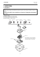
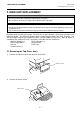
2.1 Removing the Top Cover Ass’y
2- 2
3) Remove the two TP-4x10 screws securing the Top Cover Ass’y to the Bottom Cover. And then,
remove the Top Cover Ass’y in the direction indicated by the arrow.
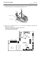
4) Remove the four connectors (CN8, 10, 11, 17) connected to the MAIN PC Board from the
following units, respectively.
CN8 (14 pins) and CN17 (15 pins) from the Keyboard Unit
CN10 (12 pins) from the FIU PC Board
CN11 (9 pins) from the Control Lock
TP-4x10
TP-4x10
Top Cover Ass’y
Bottom Cover
U25
ROM
U24
U26
RAM
RAM
CN8
CN17
CN11
Keyboard-1
Keyboard-2
Control Lock
U19
CPU
U14
Gate Array
CN2
Li-Battery
CN13
Expansion Memory
CN10
FIU PC Board
CN401
Transformer
CN9
(not used)
CN12
CN14
CN15
RS-232C #1
RS-232C #2
RS-232C #3
CN7
Drawer Sensor
CN16
Drawer
Buzzer
Receipt Printer
Motor, Sensor
Receipt Printer
Head
Journal Printer
Head
Journal Printer
Motor, Sensor
CN5 (not used)
Winding
Motor
Auto
Cutter
CN6 (not used)
CN504
CN503
CN505
CN501 CN502
CN506