
Operation Manual


2. MAIN UNIT REPLACEMENT
EO18-11004A
2.2 Note for Attaching the Top Cover Ass’y
2- 3
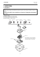
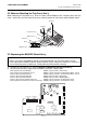
2.2 Note for Attaching the Top Cover Ass’y
When attaching the Top Cover Ass’y, fit the six hooks into the Bottom Cover, and then attach the Top
Cover. At this time, be careful not to catch any cables between the Top Cover and the Bottom Cover.
2.3 Replacing the MAIN PC Board Ass’y
CAUTION!
1. When you replace the MAIN PC Board, all programmed data and sales data will be cleared.
2. After replacing the MAIN PC Board, plug the power cord to charge the machine for 48 hours or
more and then perform a RAM clear, resulting that the ECR performs normally.
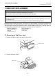
1) Remove the Top Cover Ass’y. (Refer to Section 2.1 Removing the Top Cover Ass’y.)
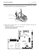
2) Disconnect the fourteen cables from the MAIN PC Board as shown below.
CN2 (2 pins) from the Li-Battery CN401 (7 pins) from the Transformer
CN7 (2 pins) from the Drawer Sensor CN501 (12 pins) from the Receipt Printer Motor, Sensor
CN12 (6 pins) from RS-232C #1 CN502 (12 pins) from the Journal Printer Motor, Sensor
CN14 (5 pins) from RS-232C #2 CN503 (4 pins) from the Auto Cutter
CN15 (5 pins) from RS-232C #3 CN504 (3 pins) from the Winding Motor
CN16 (3 pins) from the Drawer Solenoid CN505 (14 pins) from the Receipt Printer Head
CN9 (7 pins) from the Binary Lock (FS-1535 only) CN506 (14 pins) from the Journal Printer Head
TP-4x10
TP-4x10
Top Cover Ass’y
Bottom Cover
Top Cover
Hook
Bottom Cover
U25
ROM
U24
U26
RAM
RAM
CN8
CN17
CN11
Keyboard-1
Keyboard-2
Control Lock
U19
CPU
U14
Gate Array
CN2
Li-Battery
CN13
Expansion Memory
CN10
FIU PC Board
CN401
Transformer
CN9
Binary Lock
(FS-1535 only)
CN12
CN14
CN15
RS-232C #1
RS-232C #2
RS-232C #3
Drawer Sensor
CN16
Drawer
Buzzer
Receipt Printer
Motor Sensor
Receipt Printer
Head
Journal Printer
Head
Journal Printer
Motor Sensor
CN5 (not used)
Winding
Motor
Auto
Cutter
CN6 (not used)
CN504
CN503
CN505
CN501 CN502
CN506
CN7