
Operation Manual


2. MAIN UNIT REPLACEMENT
EO18-11004A
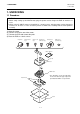
2.3 Replacing the MAIN PC Board Ass’y
2- 4
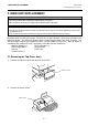
3) Remove the six TP-3x8 screws and the MAIN PC Board Ass’y from the Bottom Cover.
4) Replace the MAIN PC Board Ass’y with the new one, and then reassemble in the reverse order of
removal.
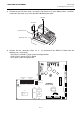
NOTE: After replacing the MAIN PC Board Ass’y, lead the Drawer Sensor Cable, Drawer
Solenoid Cable, and the RS-232C #1/#2/#3 Cables as the figure shows below.
5) Make Print Test in Diagnostic Test to check the performance. (See Section 4.1 Print Test.)
TP-3x8
Bottom Cover
TP-3x8
TP-3x8
TP-3x8
MAIN PC Board Ass’y
Transformer
Bottom Cover
Cable Clamp
Power Cord
MAIN PC Board
Drawer Sensor Cable and
Drawer Solenoide Cable
RS-232C #1/#2/#3 Cables