
Manual


÷
÷
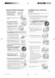
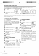
ANTENNA/CATV CONNECTIONS
Choose one of the following seven connections, based on your
equipment and service:
CombinationVHF/UHFantenna
Single 75 ohm cable
(or)
ToANTinput
Single 300 ohm twin-lead wire* _ onbackotTV
*For best perforrnance, #you havea splitter connected, fernove TRANSFORMER
the splitter and comiectthe single wire to the ttansfomTec (riot supplied)
andthen to the TV_ antennainput (as illustrated here)
Separate VHFand UHF antennas or
Combination VHF/UHFantenna with separate cables/wires
UHF Antenna
_ 300 ohm twin-lead wire __=_ ToANTklput
VHF Antenna
75 ohm cable | COMBINER
(netsupplied)
(or)
UHF Antenna
_r_ 300 ohm twin-lead wire
............................................................................................=:_1_ I ToANTklput
VHFAntenna _
300 ohm twin-lead wire*_J CT_R
_ (n0t supplied)
TRANSFORMER
(notsupplied)
Cable TV service ToANTklput
(or) ToANTinput
onbackofTV
FromTvserviceCable_CONVERTER/DESCRAMBLER I
(or) ToANTi,,put
mNICONVERTER/DESCRAMBLER)Nm _,,_,o__ _
From cable _ ' / ' _ .........
TVservicem_fJSPLlTTER A BSWITCHI_____r._mmmmc::z:3_J
Combination VHF/UHF antenna (Single 75 ohm cable or 300
ohm twin-lead wire)
Connect the 75 ohm cable from a combination VHF/UHF
antenna to the antenna jack.
If your combination antenna has a 300 ohm twin-lead wire, use
the 300-75 ohm matching transformer (not supplied).
Combination VHF/UHF antenna (Separate VHF and UHF 300
ohm twin-leads)
Connect the UHF twin-lead wire to a combiner (not supplied).
Connect the VHF twin-lead to the 300-75 ohm matching
transformer (not supplied). Attach the transformer to the
combiner. Attach the combiner to the antenna jack.
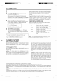
Separate VHF/UHF antennas
Connect the 75 ohm cable from the VHF antenna and the UHF
antenna twin-lead to a combiner (not supplied). Attach the
combiner to the antenna jack.
NOTE: If your VHF antenna has a twin-lead wire, use the 300-75
ohm matching transformer (not supplied), then connect the trans-
former to the combiner.
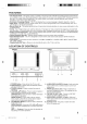
For subscribers to basic cable TV service
For basic cable service not requiring a converter/descrambler
box, connect the CATV 75 ohm coaxial cable directly to the
antenna jack on the back of the television.
For subscribers to scrambled cable TV service
If you subscribe to a cable service which requires the use of a
converter/descrambler box, connect the incoming cable to the
converter/descrambler box and connect the output of the box to
the antenna jack on the back of the television. Follow the
connections shown left. Set the television to the output of the
converter/descrambler box (usually channel 3 or 4) and use the
converter/descrambler box to select channels.
For subscribers to unscrambled basic cable with scrambled
premium channels
If you subscribe to a cable service in which basic cable channels
are unscrambled and premium channels require the use of a
converter/descrambler box, you may wish to use a two-set signal
splitter (sometimes called a "two-set coupler") and an A/B switch
box from the cable installer or an electronics supply store. Follow
the connections shown left. With the switch in the "B" position, you
can directly tune any nonscrambled channels on your TV. With
the switch in the "A" position, tune your TV to the output of the
converter/descrambler box (usually channel 3 or 4) and use the
box to tune scrambled channels.
This television has an extended tuning range and can tune most
cable channels without using a cable company supplied
converter box. Some cable companies offer "premium pay
channels" in which the signal is scrambled. Descrambling these
signals for normal viewing requires the use of a descrambler
device which is generally provided by the cable company.
CONNECTION TO OTHER EQUIPMENT
The exact arrangement you use to interconnect various video and audio components to the TV is dependent on the model and features
of each component. Check the owner's manual provided with each component for the location of video and audio inputs and outputs.
The following connection diagrams are offered as suggestions. You may need to modify them to accommodate your particular
assortment of components.
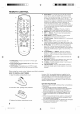
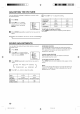
TV/VIDEO SELECTION
To view the picture from a VCR, camcorder, or TV game, you
must put the TV in VIDEO mode first. Press TV/WDEO to
select VIDEO mode. The word "VIDEO1" or "VIDEO2"
displays briefly on-screen. Press TV/WDEO again to return to
TV mode.
v,oeo-] [
VlDEOI/ Front of TV
J
ttt
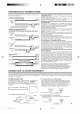
To Audio/Video OUT _ (not supplied) t_
2. To connect the TV to a VIDEO Game
The TV also can be used as a display device for many video
games. However, due to the wide variety of different types of
signal generated by these devices and subsequent hook-up
variations required, they have not all been included in the
suggested connection diagrams. You will need to consult each
component's owner's manual for additional information.
1. To connect the TV to a VCR
VCR Rear ofTV _ VIDEO
TOdAU_T; _ _ AUD,(_(R) _ AU-D,O(L}
(not supplied) !
3. To connect the TV to a camcorder
To playback from the camcorder, connect the camcorder to
the TV as shown.
Front ofTV
r_
ToAMOUT jack
(not supplied) _
7
÷
3M91301A-E P02-07
÷
13/2/04, 2:06