FILE NO. A07-003 SERVICE MANUAL AIR-CONDITIONER SPLIT TYPE INDOOR UNIT RAV-SM564UT-E RAV-SM1104UT-E RAV-SM804UT-E RAV-SM1404UT-E OUTDOOR UNIT RAV-SP1104AT-E RAV-SP1404AT-E RAV-SP1104ATZ-E RAV-SP1404ATZ-E RAV-SP1104ATZG-E RAV-SP1404ATZG-E R410A PRINTED IN JAPAN, Dec.
Adoption of New Refrigerant This Air Conditioner is a new type which adopts a new refrigerant HFC (R410A) instead of the conventional refrigerant R22 in order to prevent destruction of the ozone layer. WARNING Cleaning of the air filter and other parts of the air filter involves dangerous work in high places, so be sure to have a service person do it. Do not attempt it yourself. The cleaning diagram for the air filter is there for the service person, and not for the customer. CONTENTS SAFETY CAUTION .....
6. REFRIGERANT R410A ........................................................................... 33 6-1. 6-2. 6-3. 6-4. 6-5. 6-6. Safety During Installation/Servicing ............................................................... Refrigerant Piping Installation ....................................................................... Tools .................................................................................................................. Recharging of Refrigerant..............................
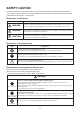
SAFETY CAUTION The important contents concerned to the safety are described on the product itself and on this Service Manual. Please read this Service Manual after understanding the described items thoroughly in the following contents (Indications/Illustrated marks), and keep them.
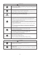
WARNING Check earth wires. Before troubleshooting or repair work, check the earth wire is connected to the earth terminals of the main unit, otherwise an electric shock is caused when a leak occurs. If the earth wire is not correctly connected, contact an electric engineer for rework. Do not modify the products. Do not also disassemble or modify the parts. It may cause a fire, electric shock or injury. Prohibition of modification. Use specified parts. Do not bring a child close to the equipment.
WARNING Insulator check Ventilation After the work has finished, be sure to use an insulation tester set (500V Megger) to Ω or more between the charge section and the non-charge check the resistance is 2MΩ metal section (Earth position). If the resistance value is low, a disaster such as a leak or electric shock is caused at user’s side. When the refrigerant gas leaks during work, execute ventilation. If the refrigerant gas touches to a fire, poisonous gas generates.
• New Refrigerant (R410A) This air conditioner adopts a new HFC type refrigerant (R410A) which does not deplete the ozone layer. 1. Safety Caution Concerned to New Refrigerant The pressure of R410A is high 1.6 times of that of the former refrigerant (R22). Accompanied with change of refrigerant, the refrigerating oil has been also changed.
4. Tools 1. Required Tools for R410A Mixing of different types of oil may cause a trouble such as generation of sludge, clogging of capillary, etc. Accordingly, the tools to be used are classified into the following three types.
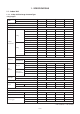
1. SPECIFICATIONS 1-1. Indoor Unit 1-1-1. 4-Way Air Discharge Cassette Type Indoor unit RAV-SM 564UT-E 804UT-E 1104UT-E 1404UT-E Outdoor unit RAV-SP 562AT(Z)(ZG)-E 802AT(Z)(ZG)-E Cooling capacity (kW) 5.3 7.1 10.0 12.5 Heating capacity (kW) 5.6 8.0 11.2 14.0 Model Power supply 1104AT(Z)(ZG)-E 1404AT(Z)(ZG)-E 1 phase 230V (220 – 240V) 50Hz Running current (A) Power consumption(kW) Power factor (%) 7.17 – 6.57 8.95 – 8.21 10.36 – 9.49 14.66 – 13.44 1.53 1.93 2.
Indoor unit RAV- SM564UT-E SM804UT-E SM1104UT-E SM1404UT-E Outdoor unit RAV- SM563AT-E SM803AT-E SM1103AT-E SM1403AT-E Cooling capacity (kW) 5.3 6.7 10.0 12.0 Heating capacity (kW) 5.6 8.0 11.2 14.0 (A) 7.89 – 7.24 9.97 – 9.12 14.61 – 13.40 17.62 – 16.14 1.65 2.09 3.11 3.74 95 95 97 96 3.21 3.21 3.22 3.21 Energy efficiency class ∗ A A A A Energy rating ∗∗ — — — — 6.89 – 6.32 10.83 – 9.90 13.38 – 12.38 17.88 – 15.87 1.44 2.21 2.93 3.
Indoor unit 1 RAV- SM564UT-E SM804UT-E Indoor unit 2 RAV- SM564UT-E SM804UT-E Outdoor unit RAV- SP1104AT(Z)(ZG)-E SP1404AT(Z)(ZG)-E Cooling capacity (kW) 10.0 12.5 Heating capacity (kW) 11.2 14.0 Model Indoor unit Power supply 1 phase 230V (220 – 240V) 50Hz Running current Cooling (A) 10.36 – 9.49 14.66 – 13.44 Power consumption (kW) 2.21 3.16 Power factor (%) 97 98 4.52 3.96 A A (A) 10.96 – 10.05 14.89 – 13.65 Power consumption (kW) 2.34 3.
Indoor unit 1 RAV- SM564UT-E SM804UT-E Indoor unit 2 RAV- SM564UT-E SM804UT-E Outdoor unit RAV- SM1103AT-E SM1403AT-E Cooling capacity (kW) 10.0 12.5 Heating capacity (kW) 11.2 14.0 Model Indoor unit Power supply 1 phase 230V (220 – 240V) 50Hz Running current Cooling (A) 14.40 – 13.20 20.57 – 18.97 Power consumption (kW) 3.11 4.09 Power factor (%) 98 95 3.22 3.06 A B (A) 14.40 – 13.20 17.74– 16.08 Power consumption (kW) 2.93 4.00 Power factor (%) 98 99 3.
1-1-2. Concealed Duct Type Indoor unit RAV-SM 562BT-E 802BT-E 1102BT-E 1402BT-E Outdoor unit RAV-SP 562AT(Z)(ZG)-E 802AT(Z)(ZG)-E Cooling capacity (kW) 5.0 7.1 10.0 12.5 Heating capacity (kW) 5.6 8.0 11.2 14.0 Model Power supply 1104AT(Z)(ZG)-E 1404AT(Z)(ZG)-E 1 phase 230V (220 – 240V) 50Hz Running current (A) 6.51 – 5.97 9.74 – 8.93 13.78 – 12.63 17.76 – 16.28 1.39 2.10 2.94 3.83 97 98 97 98 3.60 3.38 3.40 3.
Indoor unit 1 RAV- SM562BT-E SM802BT-E Indoor unit 2 RAV- SM562BT-E SM802BT-E Outdoor unit RAV- SP1104AT(Z)(ZG)-E SP1404AT(Z)(ZG)-E Cooling capacity (kW) 10.0 12.5 Heating capacity (kW) 11.2 14.0 Model Indoor unit Power supply 1 phase 230V (220 – 240V) 50Hz Running current Cooling (A) 13.78 – 12.63 17.76 – 16.28 Power consumption (kW) 2.94 3.83 Power factor (%) 97 98 3.4 3.26 A A (A) 12.98 – 11.90 15.82 – 14.50 Power consumption (kW) 2.77 3.
1-1-3. Under Ceiling Type Indoor unit RAV-SM 562CT-E 802CT-E Outdoor unit RAV-SP 562AT(Z)(ZG)-E 802AT(Z)(ZG)-E Cooling capacity (kW) 5.0 7.1 10.0 12.5 Heating capacity (kW) 5.6 8.0 11.2 14.0 1102CT-E 1402CT-E Model Power supply 1104AT(Z)(ZG)-E 1404AT(Z)(ZG)-E 1 phase 230V (220 – 240V) 50Hz Running current (A) 6.61 – 6.06 9.47 – 8.93 12.51 – 11.47 17.30 – 15.86 1.41 2.1 2.67 3.73 97 98 97 98 3.55 3.38 3.75 3.35 A A A A 7.03 – 6.44 10.20 – 9.
Indoor unit 1 RAV- SM562CT-E SM802CT-E Indoor unit 2 RAV- SM562CT-E SM802CT-E Outdoor unit RAV- SP1104AT(Z)(ZG)-E SP1404A(Z)(ZG)-E Cooling capacity (kW) 10.0 12.5 Heating capacity (kW) 11.2 14.0 Model Indoor unit Power supply 1 phase 230V (220 – 240V) 50Hz Running current Cooling (A) 12.51 – 11.47 17.30 – 15.86 Power consumption (kW) 2.67 3.73 Power factor (%) 97 98 3.75 3.35 A A (A) 12.28 – 11.25 16.93 – 15.52 Power consumption (kW) 2.62 3.
1-1-4. High Wall Type Indoor unit RAV- SM562KRT-E SM802KRT-E Outdoor unit RAV- SP562AT(Z)(ZG)-E SP802AT(Z)(ZG)-E Cooling capacity (kW) 5.0 6.9 Heating capacity (kW) 5.6 8.0 Model Power supply 1 phase 230V (220 – 240V) 50Hz Running current (A) 8.33 – 7.63 13.15 – 12.05 1.39 2.4 95 94 3.60 2.88 Energy efficiency class ∗ A C Energy rating ∗∗ — — 8.14 – 7.46 12.91 – 11.84 1.55 2.4 95 94 3.61 3.33 Energy efficiency class ∗ A C Energy rating ∗∗ — — 15.
Indoor unit 1 RAV- SM562KRT-E SM802KRT-E Indoor unit 2 RAV- SM562KRT-E SM802KRT-E Outdoor unit RAV- SP1104AT(Z)(ZG)-E SP1404AT(Z)(ZG)-E Cooling capacity (kW) 10.0 12.3 Heating capacity (kW) 11.2 14.0 Model Indoor unit Power supply 1 phase 230V (220 – 240V) 50Hz Running current Cooling (A) 12.98 – 11.90 18.00 – 16.50 Power consumption (kW) 2.77 3.88 Power factor (%) 97 98 3.61 3.17 A B (A) 13.12 – 12.03 17.76 – 16.28 Power consumption (kW) 2.80 3.
1-1-5. Compact 4-Way Cassette (600 × 600) Type RAV-SM562MUT-E Indoor unit Model Outdoor unit RAV-SP562AT(Z)(ZG)-E Cooling capacity (kW) 5.0 Heating capacity (kW) 5.6 Power supply 1 phase 230V Running current (A) 6.6 – 7.15 Power consumption(kW) Power factor 1.53 97 (%) Cooling EER 3.27 Energy efficiency class A Energy rating Electrical characteristics Running current 4.5 (A) 6.62 – 7.21 Power consumption(kW) Power factor 1.54 97 (%) Heating COP 3.
Indoor unit 1 RAV- SM562MUT-E Indoor unit 2 RAV- SM562MUT-E Outdoor unit RAV- SP1104(Z)(ZG)-E Cooling capacity (kW) 10.0 Heating capacity (kW) 11.2 Model Indoor unit Power supply 1 phase 230V (220 – 240V) 50Hz Running current Cooling (A) 12.51 – 11.47 Power consumption (kW) 2.67 Power factor (%) 97 EER 3.75 Energy efficiency class ∗ Electrical characteristics Running current Heating A (A) 12.51 – 11.47 Power consumption (kW) 2.
1-2. Outdoor Unit Model name Outdoor unit RAV-SP 562AT(Z)(ZG)-E 802AT(Z)(ZG)-E 1104AT(Z)(ZG)-E 1404AT(Z)(ZG)-E 1 phase 230V (220 – 240V) 50Hz (Power exclusive to outdoor is required.) Power supply Type Compressor Hermetic compressor Motor (kW) Pole Refrigerant charged (kg) 2 2 3.75 3.75 4 4 4 4 1.5 2.1 3.1 3.1 Refrigerant control Inter connecting pipe Pulse motor valve Standard length (m) 7.5 7.5 7.5 7.5 Max.
1-3. Operation Characteristic Curve • Operation characteristic curve RAV-SP1104AT-E, SP1404AT-E / RAV-SP1104ATZ-E, SP1404ATZ-E / RAV-SP1104ATZG-E, SP1404ATZG-E 22 22 20 20 RAV-SP1104 18 RAV-SP1404 16 16 14 14 Current (A) Current (A) 18 12 10 8 RAV-SP1404 12 10 8 RAV-SP1104 6 6 • Conditions Indoor : DB27˚C/WB19˚C Outdoor : DB35˚C Air flow : High Pipe length : 7.
2. CONSTRUCTION VIEWS (EXTERNAL VIEWS) 2-1. Indoor Unit RAV-SM564UT-E 15 or more 1000 or more An obstacle 1000 or more 15 or more 860 to 910 Ceiling open dimension 1000 or more 860 to 910 Ceiling open dimension Standing 661 or less The space that is necessary for equipping and service 300 189 77 74 105 129 44 112 172 Refrigerant pipe connecting port Ø6.4 (Liquid side) Refrigerant pipe connecting port Ø12.
RAV-SM804UT-E 15 or more 1000 or more An obstacle 1000 or more 15 or more 860 to 910 Ceiling open dimension 1000 or more 860 to 910 Ceiling open dimension Standing 661 or less The space that is necessary for equipping and service Take-in port of wiring Bottom face of ceiling 105 397.5 263 157 106.5 72 241.5 Refrigerant pipe connecting port Ø15.9 (Gas side) Bottom face of ceiling 337.5 Indoor unit 189 77 74 105 Refrigerant pipe connecting port Ø9.
RAV-SM1104UT-E, RAV-SM1404UT-E 15 or more 1000 or more An obstacle 1000 or more 15 or more 860 to 910 Ceiling open dimension 1000 or more 860 to 910 Ceiling open dimension Standing 661 or less The space that is necessary for equipping and service Take-in port of wiring 77 105 129 189 44 112 172 Bottom face of ceiling 30 Refrigerant pipe connecting port Ø15.9 (Gas side) Bottom face of ceiling 129 77 10 5 137 Indoor unit 137 Refrigerant pipe connecting port Ø9.5 (Liquid side) 157 106.
7 Z views 83 74 17.5 365 17.5 128 118 327 518 178 550 178 900 600 80 Z 135 18 Details of A legs 1 2 1 2 18 30 Refrigerant pipe connecting port (Ø15.9 flare at gas side) 151 80 400 320 Details of B legs 12 Mounting bolt hole (Ø12 × 17 long hole) Refrigerant pipe connecting port (Ø9.
RAV-TWP30E2, RAV-TWP50E2 (Simultaneous Twin) B Inner diameter Ø C Inner diameter Ø D Inner diameter Ø D A A B C D Liquid side 36 14 Ø9.5 Ø6.4 Gas side 43 23 Ø15.9 Ø12.7 Liquid side 34 14 Ø9.5 Ø9.5 Gas side 44 21 Ø15.9 Ø15.
3. SYSTEMATIC REFRIGERATING CYCLE DIAGRAM 3-1. Indoor Unit • Single type (Combination of 1 indoor unit and 1 outdoor unit) (Indoor unit) Distributor (Strainer incorporated) TCJ sensor Air heat exchanger TC sensor Refrigerant pipe at liquid side (Outer dia : ØB) Strainer Refrigerant pipe at gas side (Outer dia : ØA) To outdoor unit To outdoor unit Dimension table Capillary tube specifications Outer diameter of refrigerant pipe Model AIU- Inner dia.
3-2. Outdoor Unit RAV-SP1104AT-E, SP1104ATZ-E, SP1104ATZG-E, RAV-SP1404AT-E, SP1404ATZ-E, SP1404ATZG-E TO sensor TS sensor PMV TL sensor Strainer TE sensor Check joint Capillary Ø4 ×Ø3 (6 pcs.) Cooling: High pressure Heating: Low pressure Heat exchanger Ø8, 2 rows, 52 stages FP1.45, flat fin TD sensor Distributor Refrigerant pipe at liquid side Ø9.5 Packed valve In cooling operation In heating operation Refrigerant pipe at gas side Ø15.
4. WIRING DIAGRAM 4-1.
4-2.
5. SPECIFICATIONS OF ELECTRICAL PARTS 5-1. Indoor Unit RAV-SM564UT-E, RAV-SM804UT-E No. Parts name 1 Fan motor (for indoor) 2 Thermo. sensor (TA-sensor) 3 Type SWF-230-60-2R Specifications Output (Rated) 60 W 328 mm 10 kΩ at 25°C Heat exchanger sensor (TCJ-sensor) Ø6 mm, 1000 mm 10 kΩ at 25°C 4 Heat exchanger sensor (TC-sensor) Ø6 mm, 950 mm 10 kΩ at 25°C 5 Float switch 6 Drain pump motor FS-0218-102 MDP-1401 RAV-SM1104UT-E, RAV-SM1404UT-E No.
6. REFRIGERANT R410A This air conditioner adopts the new refrigerant HFC (R410A) which does not damage the ozone layer. The working pressure of the new refrigerant R410A is 1.6 times higher than conventional refrigerant (R22).
Table 6-2-1 Thicknesses of annealed copper pipes Thickness (mm) Nominal diameter Outer diameter (mm) R410A R22 1/4 6.4 0.80 0.80 3/8 9.5 0.80 0.80 1/2 12.7 0.80 0.80 5/8 15.9 1.00 1.00 1. Joints For copper pipes, flare joints or socket joints are used. Prior to use, be sure to remove all contaminants. a) Flare Joints Flare joints used to connect the copper pipes cannot be used for pipings whose outer diameter exceeds 20 mm. In such a case, socket joints can be used.
c) Insertion of Flare Nut d) Flare Processing Make certain that a clamp bar and copper pipe have been cleaned. By means of the clamp bar, perform the flare processing correctly. Use either a flare tool for R410A or conventional flare tool. Flare processing dimensions differ according to the type of flare tool. When using a conventional flare tool, be sure to secure “dimension A” by using a gauge for size adjustment. ØD A Fig.
6˚ to 4 45˚ B A C 43˚ D to 4 5˚ Fig. 6-2-2 Relations between flare nut and flare seal surface 2. Flare Connecting Procedures and Precautions a) Make sure that the flare and union portions do not have any scar or dust, etc. b) Correctly align the processed flare surface with the union axis. c) Tighten the flare with designated torque by means of a torque wrench. The tightening torque for R410A is the same as that for conventional R22.
6-3. Tools 6-3-1. Required Tools Refer to the “4. Tools” (Page 8) 6-4. Recharging of Refrigerant When it is necessary to recharge refrigerant, charge the specified amount of new refrigerant according to the following steps. Recover the refrigerant, and check no refrigerant remains in the equipment. When the compound gauge’s pointer has indicated –0.1 Mpa (–76 cmHg), place the handle Low in the fully closed position, and turn off the vacuum pump’s power switch.
1) Be sure to make setting so that liquid can be charged. 2) When using a cylinder equipped with a siphon, liquid can be charged without turning it upside down. It is necessary for charging refrigerant under condition of liquid because R410A is mixed type of refrigerant. Accordingly, when charging refrigerant from the refrigerant cylinder to the equipment, charge it turning the cylinder upside down if cylinder is not equipped with siphon.
2. Characteristics required for flux 6-5-3. Brazing • Activated temperature of flux coincides with the brazing temperature. • Due to a wide effective temperature range, flux is hard to carbonize. • It is easy to remove slag after brazing. • The corrosive action to the treated metal and brazing filler is minimum. • It excels in coating performance and is harmless to the human body.
6-6. Instructions for Re-use Piping of R22 or R407C Instruction of Works: The existing R22 and R407C piping can be reused for our digital inverter R410A products installations. NOTE) Confirmation of existence of scratch or dent of the former pipes to be applied and also confirmation of reliability of the pipe strength are conventionally referred to the local site. If the definite conditions can be cleared, it is possible to update the existing R22 and R407C pipes to those for R410A models. 6-6-1.
6-6-5. Final Installation Checks Is there no scratch or dent on the existing pipes? Existing pipe: NO * Use a new pipes. NO Is it possible to operate the existing air conditioner? YES * After the existing air conditioner operated in cooling mode for approx. 30 minutes or longer*, recover the refrigerant. * For cooling the pipes and recovering of oil • Refrigerant recovery: Pump down method Nitrogen gas pressure 0.
6-6-6. Handling of Existing Pipe 6-6-7. Recovery Method of Refrigerant for RAV-SP1104AT-E, RAV-SP1404AT-E When using the existing pipe, carefully check it for the following: • Wall thickness (within the specified range) • Scratches and dents • Water, oil, dirt, or dust in the pipe • Flare looseness and leakage from welds • Deterioration of copper pipe and heat insulator • Use the refrigerant recovery switch SW801 on the P.C.
7. INDOOR CONTROL CIRCUIT 7-1. Indoor Controller Block Diagram 7-1-1. Connection of Main (Sub) Remote Controller Main (sub) master remote controller (Max. 2 units) Display LCD Display LED Weekly timer Function setup MCU Display LCD LCD driver Key switch Function setup CN2 MCU CN1 Key switch DC5V Remote controller communication circuit Indoor unit #1 (Master) A Power circuit DC5V ∗3 Power circuit Secondary battery #2 (Follower) A B #3 (Follower) B A B Indoor control P.C.
7-1-2. Connection of Wireless Remote Controller Kit Indoor unit #1 (Master) Wireless remote controller kit Receiver P.C. board (MCC-1504) Display LED Receive circuit Function setup SW Buzzer Grille up/down SW MCU DC5V Power circuit Remote controller communication circuit A Temporary operation SW #2 (Follower) A B #3 (Follower) B A B Indoor control P.C.
7-1-3. Connection of Both Main (Sub) Remote Controller and Wireless Remote Controller Kit Indoor unit #1 (Master) Main (sub) master remote controller (Max. 2 units) Wireless remote controller kit Receiver P.C.
7-2. Control Specifications No. 1 2 Item When power supply is reset Operation mode selection Remarks Outline of specifications 1) Distinction of outdoor unit When the power supply is reset, the outdoors are distinguished and the control is selected according to the distinguished result. 2) Setting of indoor fan speed and existence of air direction adjustment Based on EEPROM data, select setting of the indoor fan speed and the existence of air direction adjustment.
No. 3 Item Room temp. control (Continued) Outline of specifications Remarks 2) Using the Item code 06, the setup temperature in heating operation can be corrected. Setup data 0 2 4 6 Setup temp. correction +0°C +2°C +4°C +6°C Shift of suction temperature in heating operation Setting at shipment Setup data 4 Automatic capacity control (GA control) 5 Automatic cooling/heating control 2 1) Based on the difference between Ta and Ts, the operation frequency is instructed to the outdoor unit.
No. Item 6 Air speed selection Outline of specifications Remarks 1) Operation with (HH), (H), (L) or [AUTO] mode is carried out by the command from the remote controller. (2) When the air speed mode [AUTO] is selected, the air speed varies by the difference between Ta and Ts. HH > H+ > H > L+ > L > UL Ta (˚C) HH (HH) A B C H+ (HH) D +3.0 +2.5 +2.0 +1.5 +1.0 +0.5 Tsc –0.
No. Item 6 Air speed selection (Continued) Remarks Outline of specifications Item code [5d] SW501 (1)/(2) Tap Standard Type 1 Type 3 Type 6 0 1 3 6 OFF/OFF ON/OFF OFF/ON ON/ON HEAT COOL HEAT COOL HEAT COOL HEAT COOL F1 HH F2 HH F3 H+ F4 HH HH HH HH H+, H H+, H H+, H H+, H L+, L L+, L Selection of high ceiling type Item code: [5d] or selection of high ceiling on P.C.
No. 7 Item Cool air discharge preventive control Outline of specifications 1) In heating operation, the indoor fan is controlled based on the detected temperature of Tc sensor or Tcj sensor. As shown below, the upper limit of the revolution frequency is restricted. However B zone is assumed as C zone for 6 minutes and after when the compressor activated. In defrost operation, the control value of Tc is shifted by 6°C.
No. Item Outline of specifications 9 High-temp. release control 1) The heating operation is performed as follows based on the detected temperature of Tc sensor or Tcj sensor. • When [M] zone is detected, the commanded frequency is decreased from the real operation frequency. After then the commanded frequency changes every 30 seconds while operation is performed in [M] zone. • In [N] zone, the commanded frequency is held.
No. Item Outline of specifications Remarks 12 Louver control 1) Louver position setup • When the louver position is changed, the position moves necessarily to downward discharge position once to return to the set position. • The louver position can be set up in the following operation range. The louver position at horizontal discharge position at under SM80 differs from that at over SM110.
No. Item Outline of specifications 12 Louver control (Continued) <> • For the Swing mode, the following three types of modes are SWING/FIX selectable and settable by keeping Swing/Direction button pushed for 4 seconds or more on the remote controller. Standard (4 pieces: same phase) swing → Data: [0001 (At shipment)] When Swing operation is selected, four louvers align at the horizontal discharge position and then start the Swing operation at the same time.
No. Item 12 Louver control (Continued) Outline of specifications • If there is the locked louver in the unit, [ ] goes on the remote controller screen. • While the following controls are performed, the louvers operate even if executing the louver lock. Control which ignores lock Objective louver No. Operation stop Full-close position When heating operation started Horizontal discharge position Heating thermo.
No. Item Outline of specifications Remarks 15 Filter sign display (Except wireless type) 1) The operation time of the indoor fan is calculated, the filter reset signal is sent to the remote controller when the specified time (2500H) has passed, and it is displayed on LCD. 2) When the filter reset signal has been received from the remote controller, time of the calculation timer is cleared. In this case, the measurement time is reset if the specified time has passed, and display on LCD disappears.
No. 19 Item DC motor Remarks Outline of specifications 1) When the fan operation has started, positioning of the stator and the rotor are performed. (Moves slightly with tap sound) 2) The motor operates according to the command from the indoor controller. Notes) • When the fan rotates while the air conditioner stops due to entering of outside air, etc, the air conditioner may operate while the fan motor stops. • When a fan lock is found, the air conditioner stops, and an error is displayed.
No. Item Outline of specifications 22 8°C heating/ Frost protective operation 1) This functional is intended for the cold latitudes and performs objective heating operation (8°C heating operation). 2) This function is valid only for combination with the outdoor units (Super Digital Inverter (SDI) 4-series outdoor units). 3) Using the indoor DN code [D1] (1 bit), Valid/Invalid of this function is set up at the customer’s side.
Connector No. Humidifier output (∗) CN66 Ventilation output HA Option output – 58 – Outside error input AUTO up/down grille (∗) Pin No.
Indoor/Outdoor inter-unit cable CN67 (Black), AC230V Optional power supply CN309 (Yellow), AC230V DC fan return CN334 (White) – 59 – TCC-LINK adapter CN50 (White), DC12V, 5V DISP CN72 (White), DC5V CHK CN71 (White), DC5V Outside error input CN80 (Green), DC12V Automatic up/down grille CN20 (Blue), DC12V EXCT CN73 (Red), DC5V Drain pump CN504 (White), DC12V Float switch CN34 (Red), DC12V Filter CN70 (White), DC5V TCJ sensor CN102 (Red), DC5V TA sensor CN104 (Yellow), DC5V TC sensor CN101 (Black
8. CIRCUIT CONFIGURATION AND CONTROL SPECIFICATIONS 8-1. Outdoor Controls 8-1-1. Print Circuit Board RAV-SP1104AT-E, RAV-SP1404AT-E RAV-SP1104ATZ-E, RAV-SP1404ATZ-E RAV-SP1104ATZG-E, RAV-SP1404ATZG-E Fan motor output (Lower side) CN300 (White) Fan motor output (Upper side) CN400 (White) Compressor output terminal CN202 CN201 CN200 Electrolytic condenser Case thermostat connector CN609 (Blue) Power supply circuit protective fuse F100 250V, 3.
8-2. Outline of Main Controls 1. PMV (Pulse Motor Valve) control 1) PMV is controlled between 30 and 500 pulsed during operation. 2) In cooling operation, PMV is usually controlled with the temperature difference between TS sensor and TC sensor aiming 1 to 4K as the target value. 3) In heating operation, PMV is usually controlled with the temperature difference between TS sensor and TE sensor aiming –1 to 4K as the target value.
3. Outdoor fan control Revolution frequency allocation of fan taps [rpm] SP110 SP140 W1 W2 W3 W4 W5 W6 W7 W8 W9 WA WB WC WD WE Up 200 240 240 260 320 380 480 500 530 610 640 660 720 780 Down — — 200 280 360 400 500 520 550 630 660 700 740 820 3-1) Cooling fan control The outdoor fan is controlled by TL sensor, TO sensor and the operation frequency. The outdoor fan is controlled by every 1 tap of DC fan control (14 taps).
4. Coil heating control 1) This control function heats the compressor by turning on the stopped compressor instead of a case heater. It purposes to prevent stagnation of the refrigerant inside of the compressor. 2) As usual, turn on power of the compressor for the specified time before a test run after installation; otherwise a trouble of the compressor may be caused.
7. Current release value shift control Current release control value (11) [A] 1) This control purposes to prevent troubles of the electronic parts such as the compressor driving elements and the compressor during cooling operation. 2) The current release control value (I1) is selected from the following table according to TO sensor value. Temperature range SP110, SP140 44°C ≤ To 15.0 39°C ≤ To < 44°C 17.7 To < 39°C 20.0 TO error 15.0 8.
10. Defrost control 1) In heating operation, defrost operation is performed when TE sensor satisfies any condition in A zone to D zone. 2) During defrosting operation, it finishes if TE sensor continued 12°C or higher for 3 seconds or continued 7°C ≤ TE < 12°C for 1 minute. The defrost operation also finishes when it continued for 10 minutes even if TE sensor temperature was 7°C or lower. 3) After defrost operation was reset, the compressor stopped for approx.
9. TROUBLESHOOTING 9-1. Summary of Troubleshooting 1. Before troubleshooting 1) Required tools/instruments • + and – screwdrivers, spanners, radio cutting pliers, nippers, push pins for reset switch • Tester, thermometer, pressure gauge, etc. 2) Confirmation points before check a) The following operations are normal. 1. Compressor does not operate.
1. Before troubleshooting 1) Required tools/instruments • + and – screwdrivers, spanners, radio cutting pliers, nippers, etc. • Tester, thermometer, pressure gauge, etc. 2) Confirmation points before check a) The following operations are normal. 1. Compressor does not operate.
9-2. Troubleshooting 9-2-1. Outline of judgment The primary judgment to check whether a trouble occurred in the indoor unit or outdoor unit is carried out with the following method. Method to judge the erroneous position by flashing indication on the display part of the indoor unit (sensors of the receiving part) The indoor unit monitors the operating status of the air conditioner, and the blocked contents of self-diagnosis are displayed restricted to the following cases if a protective circuit works.
Lamp indication Operation Timer Ready Check code F01 F02 Alternate flash P10 Cause of trouble occurrence Heat exchanger sensor (TCJ) error Heat exchanger sensor (TC) error Heat exchanger sensor (TA) error Indoor unit sensor error F04 F06 Operation Timer Ready F07 F08 Alternate flash F12 F13 Discharge temp. sensor (TD) error Temp. sensor (TE) error Temp. sensor (TL) error Temp. sensor (TO) error Temp. sensor (TS) error Temp. sensor (TH) error Temp.
9-2-2.
9-2-3.
Check Code List (Outdoor) ¡ : Go on, ¥ : Flash, l : Go off Remote controller indication F04 Sensor lamp part Block indication Operation Timer Ready Flash ALT ¥ ¥ ¡ ¥ ¥ ¥ ¥ ¥ ¥ ¥ ¥ ¥ ¥ ¥ ¥ ¡ L29 ¥ P03 E01 ¥ ¥ ¥ ¥ ¥ ¥ ¥ ¥ ¥ ¥ E02 ¥ F06 F08 F07 F12 F13 F15 F31 H01 H02 H03 H04 L10 – 72 – P04 P05 P07 P15 P20 P22 P26 P29 E03 E04 E08 E09 E10 E18 L03 L07 L08 L09 L30 P19 ¥ ¥ ¥ ¥ ¥ ¥ ¥ l l l l ¥ l ¥ ¥ ¥ ¥ ¥ ¥ ¥ ¥ ¥ ¥ ¡ ¡ ¡ ¡ ¡ ¡ ¡ l l l l ALT (Alternate): Alternate flashing when there are two fla
¡ : Go on, ¥ : Flash, l : Go off Remote controller indication F01 F02 F10 F29 P01 P10 P12 P31 — Sensor lamp part Block indication Operation Timer Ready Flash ALT ¥ ¥ ALT ¥ ¥ ALT ¥ ¥ SIM ¥ ¥ ALT ¥ ¥ ALT ¥ ¥ ALT ¥ ¥ ALT ¥ ¥ l l l — l By unit with warning No. — L20 l l l l ALT — ¥ ¡ — ALT (Alternate): Alternate flashing when there are two flashing LED Representative defective position Indoor unit Heat exchanger sensor (TCJ) error Indoor unit Heat exchanger sensor (TC) error Indoor unit Room temp.
Error mode detected by indoor unit Operation of diagnostic function Check code Cause of operation E03 No communication from remote controller (including wireless) and communication adapter E04 The serial signal is not output from outdoor unit to indoor unit. • Miswiring of inter-unit wire • Defective serial sending circuit on outdoor P.C. board • Defective serial receiving circuit on indoor P.C.
Error mode detected by remote controller or central controller (TCC-LINK) Operation of diagnostic function Check code Cause of operation Status of air conditioner Judgment and measures Condition Power supply error of remote controller, Indoor EEPROM error 1. Check remote controller inter-unit wiring. 2. Check remote controller. 3. Check indoor power wiring. 4. Check indoor P.C. board. 5. Check indoor EEPROM. (including socket insertion) → Automatic address repeating phenomenon generates.
Error mode detected by outdoor unit The check code has been ramified from 4 series and after. The ramified check code is displayed only when both the indoor unit and the outdoor unit are 4 series and after. (Ex. Combination of RAV-SM1404UT-E with RAV-SP1404AT-E) When the indoor unit is 3 series and before, the conventional check code is displayed. (Ex. Combination of RAV-SM1402BT-E and RAV-SP1404AT-E: Outdoor unit only is 4 series.
Operation of diagnostic function Check code Indoor unit before 3 series after 4 series P03 P03 Judgment and measures Cause of operation Status of air conditioner Condition Discharge temp. error ∗ Discharge temp. (TD) over specified value was detected. Stop Displayed when error is detected 1. Check refrigerating cycle (Gas leak) 2. Trouble of electronic expansion valve 3. Check discharge temp. sensor (TD). 1. 2. 3. 4. 5. Check case thermostat and connector.
9-2-4. Diagnostic Procedure for Each Check Code (Indoor Unit) Check code [E01 error] Is inter-unit cable of A and B normal? NO Correct inter-unit cable of remote controller YES Correct connection of connector. Check circuit wiring. NO Check power connection of indoor unit. (Turn on power again.) NO Check indoor P.C. board (MCC-1570). Defect → Replace YES Correct a master unit/a follower unit.
[E04 error] NO Does outdoor operate? Is group address setup of remote controller correct? YES NO Check Item code [14]. YES Are wiring in indoor unit and 1, 2, 3 inter-unit cables correct? NO Correct wiring and inter-unit cables. NO Correct wiring of connector and terminal blocks. NO Check indoor P.C. board. Defect → Replace YES Are wirings of terminal blocks (1, 2, 3) wired to CN04 normal? YES Does D502 (Orange LED) flash after power supply turned on again? YES Check indoor P.C. board.
[E18 error] Is inter-unit cable of A and B normal? NO Correct inter-unit cable of remote controller. YES Correct connection of connector. Check circuit wiring. NO Check power connection status of indoor unit (Connect again).
[L20 error] Are wiring connections to communication lines U3 and U4 normal? NO Correct wiring connection. YES Is not the multiple same central control system addresses connected? YES Correct central control system address. NO Check central controller (including network adapter) and indoor P.C. board (MCC-1570). Defect → Replace [L30 error] Are outside devices of connector CN80 connected? NO Check indoor P.C. board (MCC-1570). Defect → Replace NO Check outside devices.
[P10 error] Is connection of float switch connector (Indoor control board CN34) normal? NO Correct connection of connector. YES NO YES Does float switch work? Is circuit wiring normal? YES NO Check and correct wiring and wire circuit. NO Does drain pump work? YES Is power of drain pump turned on? ∗ NO YES Are connector pins 1 and 2 at drain pump unit side shorted (Resistance value 0)? NO YES Replace drain pump and indoor P.C. board (MCC-1570). Check the drain pipe, etc. Check indoor P.C.
[P12 error] Turn off the power. Is there no connection error or disconnection on connectors CN333 and CN334 of indoor unit P.C. board (MCC-1570)? YES Correct connection of connector. CN333 NO Remove connectors CN333 and CN334 of indoor unit P.C. board (MCC-1570). CN334 Does the fan rotate without trouble when handling the fan with hands? NO Replace indoor fan motor. YES Are resistance values between phases at fan motor connector CN333 motor side of indoor P.C.
[F02 error] Is connection of TC sensor connector (CN101 on Indoor P.C. board) correct? NO Correct connection of connector. YES Are characteristics of TC sensor resistance value normal? YES NO Replace TC sensor. ∗ Refer to Characteristics-2. Check indoor P.C. board (MCC-1570). Defect → Replace [F01 error] Is connection of TCJ sensor connector (CN102 on Indoor P.C. board) correct? NO Correct connection of connector.
[C06 error] (TCC-LINK central controller) NO Are U3 and U4 communication lines normal? Correct communication line. YES NO ∗1 Correct connection of connector. Is connection of connector normal? YES ∗1 TCC-LINK central: CN51 of TCC-LINK adapter P.C. board (MCC-1440) and CN050 of indoor P.C. board NO Are A and B communication lines normal? Check connection of A and B terminal blocks. Correct communication line of remote controller.
[E03 error] (Master indoor unit) [E03 error] is detected when the indoor unit cannot receive a signal from the remote controller (also central controller). Check A and B remote controllers and communication lines of the central control system U3 and U4. As communication is impossible, this check code [E03] is not displayed on the remote controller and the central controller. [E01] is displayed on the remote controller and [C06 error] is displayed on the central controller.
9-2-5. Diagnostic Procedure for Each Check Code (Outdoor Unit) 1) This section describes the diagnostic method for each check code displayed on the remote controller. 2) In some cases, a check code indicates multiple symptoms. In this case, confirm LED display on the outdoor P.C. board to narrow the contents to be confirmed. 3) The check code on the remote controller is displayed only when the same error occurred continuously by multiple times while LED of the outdoor P.C.
Check code Outdoor LED display [F04] ¡ ¡ l l ¡ ¡ l l ¥ l l [Discharge temp. sensor (TD) error] Is CN603 connection normal? Is resistance value of TD sensor normal? NO Correct connector. Sensor error → Replace YES ¡ [F06] Check outdoor P.C. board. Defect → Replace • There is a possibility that it is one of the following errors. Confirm LED on outdoor P.C. board to judge which error it is. Heat exchanger temp. sensor (TE) error, Heat exchanger temp.
Check code Outdoor LED display [F08] ¡ ¡ l l ¡ ¡ l l l ¥ l Check and troubleshooting (Item without special mention Indicates part of outdoor unit.) [Outside air temp. sensor (TO) error] Is CN602 connection normal? Is resistance value of TO sensor normal? NO Correct connector. Sensor error → Replace NO Correct connector. Sensor error → Replace YES ¡ Check outdoor P.C. board.
Check code Outdoor LED display [H01] l l ¡ l ¡ ¡ ¥ l l l l ¡ Check and troubleshooting (Item without special mention Indicates part of outdoor unit.) [Compressor break down] Is power supply voltage normal? AC198 to 264V NO Correct power supply line. YES Is wire connection normal? Compressor lead (Board side, Compressor side), Reactor lead, Power supply lead NO Check wire connection and correct it. YES Is it not abnormal overload? YES Correct and clear the cause.
Check code Outdoor LED display [H04] l l ¡ l ¡ ¡ l l l ¥ l ¡ Check and troubleshooting (Item without special mention Indicates part of outdoor unit.) [Case thermostat operation] Are CN609 connection and case thermostat normal? NO Correct connector. Case thermostat error → Replace NO Check outdoor P.C. board. Defect → Replace NO Repair defectives position. Recharge refrigerant.
Check code Outdoor LED display Check and troubleshooting (Item without special mention Indicates part of outdoor unit.) ∗ There is a possibility that it is one of the following errors. Confirm LED on outdoor P.C. board to judge which error it is. Communication error between MCU, Heat sing temp.
Check code Outdoor LED display [P03] ¡ ¡ ¡ l ¡ ¡ ¥ ¥ l l l ¡ Check and troubleshooting (Item without special mention Indicates part of outdoor unit.) [Discharge temp. error] Is there no gas leak? Is refrigerant charge amount adequate? NO Repair defective position. Recharge refrigerant. NO Repair defective position. Replace defective part. YES Is PMV normal? YES Is it not abnormal overload? YES Correct and clear the cause.
Check code Outdoor LED display [P07] ¡ ¡ ¡ l ¡ ¡ ¥ ¥ ¥ l l ¡ Check and troubleshooting (Item without special mention Indicates part of outdoor unit.) [Heat sink overheat error] Is there no loosening of screws of motor drive element of outdoor P.C. board Q200, Q300, Q400 and rectifier DB01, DB02, DB03? Did not forget to apply radiation grease to rear side of Q200, DB01, DB02 or DB03? YES NO Apply radiation grease to objective part. Retightening of screws.
¡ ¡ ¡ ¥ ¥ ¡ ¡ ¥ ¡ l l Is operation of 4-way valve normal? (Check pipe temp., etc. in cooling/heating operation.) Temperature sensor check TE sensor CN601 TS sensor CN600 Indoor TC sensor Defect → Correct and repair YES NO Is the coil resistance value of 4-way valve between 1.3 and 1.6kΩ? NO Replace coil of 4-way valve. YES Check operation of outdoor P.C. board. (See below.) Error Check outdoor P.C. board. Defect → replace OK Check 4-way valve.
Check code Outdoor LED display [P20] l l ¡ ¡ ¡ ¥ ¡ ¡ ¥ ¡ l l Check and troubleshooting (Item without special mention Indicates part of outdoor unit.) [High pressure protective operation] NO Is valve fully opened? Open valve fully. YES Reset the power supply and then perform test run matching to the season.
Check code Outdoor LED display [P22] l ¡ ¡ ¡ ¥ ¥ ¡ ¡ ¥ ¡ l l Check and troubleshooting (Item without special mention Indicates part of outdoor unit.) [Fan system error] Is there no problem on power supply voltage? (198 to 264V) NO Check wiring construction. Ask repair of power supply.
Temperature sensor Temperature – Resistance value characteristic table TD, TL sensors TA, TC, TCJ, TE, TS, TO sensors Representative value Representative value Resistance value (kW) Temperature (°C) (Minimum value) (Standard value) (Maximum value) Resistance value (kW) Temperature (°C) (Minimum value) (Standard value) (Maximum value) 0 32.33 33.80 35.30 0 10 19.63 20.35 21.09 10 150.5 92.76 161.3 99.05 172.7 20 12.23 12.59 12.95 20 58.61 62.36 66.26 25 9.75 10.00 10.25 25 47.
10. REPLACEMENT OF SERVICE P.C. BOARD 10-1. Indoort Unit The nonvolatile memory (hereafter called EEPROM, IC503) on the indoor unit P.C. board before replacement includes the model specific type information and capacity codes as the factory-set value and the important setting data which have been automatically or manually set when the indoor unit is installed, such as system/ indoor/group addresses, high ceiling select setting, etc.
[1] Setting data read out from EEPROM The setting data modified on the site, other than factory-set value, stored in the EEPROM shall be read out. Step 1 Push SET , CL and TEST button on the remote controller simultaneously for more than 4 seconds. ∗ When the group operation control is performed, the unit No. displayed for the first time is the header unit No. At this time, the CODE No. (DN) shows “10 ”.
[3] Writing the setting data to EEPROM The settings stored in the EEPROM of the P.C. board for indoor unit servicing are the factory-set values. Step 1 Push SET , CL and TEST buttons on the remote controller simultaneously for more than 4 seconds. * In the group control operation, the unit No. displayed for the first time is the header unit No. At this time, the CODE No. (DN) shows “ ”. Also, the fan of the indoor unit selected starts its operation and the swing operation starts if it has the louvers.
Step 6 Check the setting data displayed at this time with the setting data put down in [1]. 1. If the setting data is different, modify the setting data by pushing / buttons for the timer setting to the data put down in [1]. The operation completes if the setting data is displayed. 2. If the data is the same, proceed to next step. Step 7 / buttons for the temperature setting. Change the CODE No. (DN) by pushing As described above, check the setting data and modify to the data put down in [1].
Table 1. Setting data (CODE No.
10-2. Outdoor Unit 1. Setting the jumper wires and DIP switches Function Part name Setting J800 to J803 Model switching Cut these jumper wires according to the following table. J804 to J810 Settings Set these jumper wires to the settings of the P.C. board before replacement. SW802 Settings Set SW802 to the setting of the P.C. board before replacement. SW803 LED indication switching Set SW803 to all OFF. SW804 Special operations for service Set SW804 to all OFF.
11. SETUP AT LOCAL SITE AND OTHERS 11-1. Indoor Unit 11-1-1. Test Run Setup on Remote Controller TEST 1. When pushing button on the remote controller for 4 seconds or more, “TEST” is displayed on LC display. ON / OFF Then push button. • “TEST” is displayed on LC display during operation of Test Run. • During Test Run, temperature cannot be adjusted but air volume can be selected. • In heating and cooling operation, a command to fix the Test Run frequency is output.
(Except 4-way Air Discharge Cassette Type and Under Ceiling Type) 1 2 3 4 Remove a screw which fixes the serial olate of the receiver part on the wireless remote controller. Remove the nameplate of the reciver section by inserting a minus screwdriver, etc. into the notch at the bottom of the plate, and set the Dip switch to [TEST RUN ON]. Execute a test operation with button on the wireless remote controller. • , and LED flash during test operation.
Procedure Description Turn on power of the air conditioner. 1 The operation is not accepted for 5 minutes when power has been turned on at first time after installation, and 1 minute when power has been turned on at the next time and after. After the specified time has passed, perform a test operation. 2 Push [Start/Stop] button and change the operation mode to [COOL] or [HEAT] with [Mode] button. Then change the fan speed to [High] using [Fan] button.
11-1-2. Forced Defrost Setup of Remote Controller (For wired remote controller only) (Preparation in advance) 1 2 3 4 5 6 TEST SET CL Push + + buttons simultaneously for 4 seconds or more on the remote controller. (Push buttons while the air conditioner stops.) The first displayed unit No. is the master indoor unit address in the group control. Every pushing UNIT button, the indoor unit No. in the group control is displayed one after the other.
11-1-4. Function Selection Setup Perform setting while the air conditioner stops. 1 2 TEST SET CL Push + + buttons simultaneously for 4 seconds or more. The first displayed unit No. is the master indoor unit address in the group control. In this time, fan and louver of the selected indoor unit operate. ò UNIT LOUVER Every pushing button (button at left side), the indoor unit No. in the group control is displayed one after the other.
Function selection item No. (DN) list DN Item 01 Filter sign lighting time 0000: None 0002: 2500H 0004: 10000H 02 Filter stain level 0000: Standard 0001: Heavy stain (Half of standard time) 0000: Standard 03 Central control address 0001: No.1 unit 0099: Undecided 0099: Undecided 06 Heating suction temp.
DN Item Contents 0000: None 0000: 0.5 h to 0.012: 0 h Set when compressor-ON time is 10 to 60 minutes. 42 Self-clean operation time 45 Selection of louver horizontal discharge position 0000: Smudging-less setting 0002: Cold draft preventive setting C2 Current demand X% to outdoor unit 0050: 50% When ON-time is 60 minutes or more, the double of this operation time setting is set.
11-1-5. Wiring and Setting of Remote Controller Control 2-remote controller control (Controlled by 2 remote controllers) This control is to operate 1 or multiple indoor units are operated by two remote controllers. (Max. 2 remote controllers are connectable.
11-1-6. Monitor Function of Remote Controller Switch n Calling of sensor temperature display Each data of the remote controller, indoor unit and outdoor unit can be understood by calling the service monitor mode from the remote controller. 1 CL TEST Push + buttons simultaneously for 4 seconds to call the service monitor mode. The service monitor goes on, the master indoor unit No. is displayed at first and then the temperature of item code 00 is displayed. ò 2 TEMP.
n Calling of error history The error contents in the past can be called. 1 SET TEST Push + buttons simultaneously for 4 seconds or more to call the service check mode. Service Check goes on, the item code 01 is displayed, and then the content of the latest alarm is displayed. The number and error contents of the indoor unit in which an error occurred are displayed. TEMP.
n Indoor unit power-ON sequence Power ON • The unit without power feed waits entirely → Waiting status is released by system start • Reboot when power is fed on the way Not normal NO 3 minutes elapse Gr construction check YES Normal ∗ Gr normal 1) There is no duplicated indoor unit address. 2) There is no invalid indoor unit address. 3) Individual unit and master/follower units are not intermingled. 4) Only a unit for individual.
11-2. Setup at Local Site / Others Model name: TCB-PCNT30TLE2 11-2-1. TCC-LINK Adapter (For TCC-LINK Central Control) 1. Function This model is an optional P.C. board to connect the indoor unit to TCC-LINK (Central controller). 2. Microprocessor block diagram Indoor unit TCC-LINK adapter P.C. board CN050 Indoor control P.C.
4. Wiring specifications • Use 2-core with no polar wire. Size No. of wires • Match the length of wire to wire length of the central Up to 1000m: twisted wire 1.25mm2 control system. 2 Up to 2000m: twisted wire 2.0mm2 If mixed in the system, the wire length is lengthened with all indoor/outdoor inter-unit wire length at side. • To prevent noise trouble, use 2-core shield wire. • Connect the shield wire by closed-end connection and apply open process (insulating process) to the last terminal.
6. External view of P.C. board assembly Terminator (SW01) 52 85 7. Address setup In addition to set up the central control address, it is necessary to change the indoor unit number. (Line/Indoor/Group address). For details, refer to TCC-LINK Adapter Installation Manual. 11-3. How to Set up Central Control Address Number When connecting the indoor unit to the central control remote controller using TCC-LINK adapter, it is necessary to set up the central control address number.
2. How to confirm the central control address (New function for AMT32 remote controller) It can be confirmed even during operation or stopping. 1 2 3 Push UNIT LOUVER button for 4 seconds or more. ò In the frame at left side of the remote controller screen, the lighting set contents are displayed. During unset time, 0099 (At shipment from factory) is displayed. ò After lighting display for 3 seconds, the display automatically disappears.
3. How to set up type of swing 1 2 SWING/FIX Push for 4 seconds or more during stop of the operation. • flashes. UNIT LOUVER Push (At the left side of the button) and select the unit to be selected. • Every pushing the button, the unit No. changes. UNIT No. 1–1 UNIT No. 1–2 UNIT No. No display UNIT No. 1–3 UNIT No. 1–4 The fan of the selected unit rotates and the louver swings. 3 Using TIMER SET the swing.
4. How to set louver lock (Louver fix) 1 2 Push UNIT LOUVER (At the right side of the button) for 4 seconds or more during stop of the operation. • flashes. Electric parts box UNIT LOUVER UNIT No. 1–2 UNIT No. 1–3 Push temp. set / to display the louver No. of which air direction is to be fixed. • The selected louver swings. [F2] [F3] 02 Drain pipe 01 • Even if louver lock works, the louver temporarily moves in the following cases.
11-4. Outdoor Unit 11-4-1. Refrigerant Recovery Control The “ozone destruction coefficient” of HFC refrigerant is 0 and the discharge regulation is set as anathermal effect gas. To this model, a switch which can perform the refrigerant recovery (pump down) by the outdoor unit is mounted so that it is easy to react against the environment at reinstalling or rejection time. W804: All OFF (As initial status) The D805 (Green LED) flashes. 1) Set the mode of the indoor unit to fan mode.
11-4-3. Service Support Function (LED Display, Switch Operation) 1. Outline A various setup and operation check can be performed by DIP switches at 3 positions (SW802, SW803, SW804) and the pushdown button switches (SW800, SW801) at 2 positions. Operation part Part No. Specifications SW800 Pushdown button switch SW803 DIP switch SW801 Pushdown button switch SW804 DIP switch SW802 DIP switch Operation contents Exchanges the displayed contents of LED (D800 to D804) on the outdoor control P.C.
11-4-4. Others 1. Selection of LED display (SW800, SW803 operation) 1) Display selection list The displayed contents of LED D800 to D804 on the outdoor control P.C. board can be exchanged by operation of SW803. Switch Function / Contents Error display (Error generating at present) Error generating at present is displayed. This switch goes off when an error does not generate. Refer to Page 125.
2) Error display The error which is generating at present and the latest error (Latest error information including present) can be confirmed by lighting LED D800 toD804 on the outdoor control P.C. board. a) When all DIP switch SW803 are OFF, the status of error which is generating at present is displayed. b) <1> only of DIP switch SW803 is turned on, the error which generated before (Latest error information including present) is displayed.a) c) If there is an error, any of LED D800 to D804 goes on.
3) Sensor, current, compressor operation frequency, PMV opening display The values detected by the controller, such as temperature sensor or current value are simply confirmed.
4) Specific operation for maintenance check (SW801, SW804) The following specific operations for the maintenance check are performed by operation of SW801 or SW804. a) Select DIP switch SW804. (See table below) b) Push the pushdown button switch SW801 for approx. 1 second. c) The following functions start. While each function starts, LED D805 (Green) flashes. d) When pushing the pushdown button switch SW801 again for approx.
SW804 1 ON 2 3 4 SW804 Operation when pushdown button switch SW801 is pushed 4-way valve relay operation (For RY700, CN70 check) Turn on 4-way valve power relay (RY700). When pushing SW801 again or when 2 minutes elapsed, the operation returns to the normal control. 1 ON 2 3 4 SW804 1 ON 2 3 4 SW804 Self-hold valve separation operation (Exchange to cooling cycle) Turn on relay RY700. (CN701 between 1) and 4): Voltage=Approx.
12. ADDRESS SETUP 12-1. Address Setup
When an outdoor unit and an indoor unit are connected, or when an outdoor unit is connected to each indoor unit respectively in the group operation even if multiple refrigerant lines are provided, the automatic address setup completes with power-ON of the outdoor unit. The operation of the remote controller is not accepted while automatic address works. (Approx.12-2. Address Setup & Group Control Indoor unit No. : N - n = Outdoor unit line address N (Max. 30) - Indoor unit address n (Max. 64) Group address : 0 = Single (Not group control) 1 = Master unit in group control 2 = Sub unit in group control Master unit (= 1) : The representative of multiple indoor units in group operation sends/receives signals to/from the remote controllers and sub indoor units. (* It has no relation with an indoor unit which communicates serially with the outdoor units.
12-2-2. Automatic address example from unset address (No miscabling) 1. Standard (One outdoor unit) 1) Single 1-1 Individual (Master/Sub) 2) Gr operation (Multiple outdoor units = Miltiple indoor units only with serial communication) 2-1 Sub 1-1 Sub 4-1 Master 8-1 Sub Max.
12-3. Address Setup In case that addresses of the indoor units will be determined prior to piping work after cabling work (Manual setting from remote controller)
• Set an indoor unit per a remote controller. • Turn on power supply. 1 2 3 4 5 6 7 8 9 10 11 SET CL (Example of 2-lines cabling) (Real line: Cabling, Broken line: Refrigerant pipe) TEST OUT OUT IN IN Push + + buttons simultaneously for 4 seconds or more.n Confirmation of indoor unit No. position 1. To know the indoor unit addresses though position of the indoor unit body is recognized • In case of individual operation (Wired remote controller : indoor unit = 1 : 1) (Follow to the procedure during operation) 1 2 ON / OFF Push button if the unit stops. UNIT Push button. Unit No. 1-1 is displayed on LCD. (It disappears after several seconds.) The displayed unit No. indicate line address and indoor unit address.
Aiming in environmental preservation, it is strictly recommended to clean and maintain the indoor/outdoor units of the operating air conditioning system regularly to secure effective operation of the air conditioner. It is also recommended to maintain the units once a year regularly when operating the air conditioner for a long time. Check periodically signs of rust or scratches, etc. on coating of the outdoor units.
13. DETACHMENTS 13-1. Indoor Unit 13-1-1. 4-Way Air Discharge Cassette Type RAV-SM564UT-E, RAV-SM804UT-E, RAV-SM1104UT-E, RAV-SM1404UT-E No. Part name Suction grille Remarks Procedure Suction grille XCAUTIONX Knobs of the suction grille hook Be sure to put on the gloves at disassembling work; otherwise an injury will be caused by a part, etc. 1) Stop operation of the air conditioner and then turn off switch of the breaker.
No. Part name Remarks Procedure Electric parts cover (Continued) Adjust corner cap 1. Detachment Adjust corner cap 1) Pull knob of the adjust corner cap to the arrow direction, remove strap of the adjust corner cap from pin of the panel and then remove all the 4 corners of the cap. Knob NOTE : The knob is provided to only one side. Be sure to remove the cap of the knob side at first. Pulling direction 2. Attachment 1) Hook strap of the adjust corner cap securely to pin of the ceiling panel.
No. Part name Ceiling panel Remarks Procedure 1. Detachment 1) Carry out works of item 1 of and item 1 of . 2) Remove the flap connector (CN510, White, 20P) connected to the control P.C. board and then remove the lead wire from the clamp. NOTE : Unlock the lock of the housing part and then remove the connector. Clamp Louver motor wiring CN510 Square hole of indoor unit 3) Loosen the panel fixing 4 screws. 4) Slide the panel fixing brackets (4 positions) outward.
No. Part name Control P.C. board Remarks Procedure 1. Detachment 1) Carry out work of item 1 of . 2) Remove connectors which are connected from the control P.C. board to the other parts and then remove wiring from the clamp. CN510 : Louver motor (20P, White) CN34 : Float switch (3P, Red) CN504 : Drain pump (2P, White) CN101 : TC sensor (2P, Black) CN102 : TCJ sensor (2P, Red) CN104 : Room temp.
No. Part name Drain cap Remarks Procedure 1. Detachment Drain cap (outside) 1) Carry out work of item 1 of . 2) Loosen screws (3 positions) fixing the drain cap (outside) and then turn the drain cap to the arrow mark direction to remove it. CLOSE NOTE : The drain cap is hung down because a strap is attached to it (outside). 3) Loosen the cap by turn the drain cap (inside) for approx. 1 turn to OPEN → direction and then drain the drain water accumulated in the drain pan.
No. Part name Fan motor Remarks Procedure 1. Detachment 1) Carry out work of item 1 of . 2) Remove connectors which are connected from the control P.C. board to the other parts and then remove each wiring from the clamp. CN510 : Louver motor (20P, White) CN34 : Float switch (3P, Red) CN504 : Drain pump (2P, White) CN101 : TC sensor (2P, Black) CN102 : TCJ sensor (2P, Red) CN104 : Room temp.
No. Part name Fan motor (Continued) Remarks Procedure 2. Attachment 2) Fix the fan motor lead, TC sensor and TCJ sensor with the clamp of the bell mouth. 3) Mount the electric parts box with the fixing screws A and B. (Ø4 × 10, 3 pcs. Ø4 × 8, 1 pc.) 4) Connect the connector removed in item 1 as before and then fix wiring with the clamp. 5) Following to work of item 2 of , mount the electric parts box cover and the suction grille as before.
No. Part name Drain pump Remarks Procedure 1. Detachment 1) Carry out works of item 1 of and item 1 of . 2) Remove the drain pump connector (CN504, White, 2P) connected to the control P.C. board and then remove the lead wire from the clamp. 3) Remove the fixing screws and then remove the drain pump. (Ø4 × 10, 3 pcs.) 4) As shown in the right figure, first pull out the connecting part of the drain pump and the drain hose from the drain port and then take out the drain pump.
No. Part name Float switch assembly Remarks Procedure 1. Detachment 1) Carry out works of item 1 of and works from 1) to 5). 2) Remove the fixing screw and then remove the float switch assembly. (Ø4 × 25, 1 pc.) Float switch assembly 2. Attachment 1) Mount the float switch assembly as before with the fixing screw. Fixing screw (Ø4 × 25) NOTE : When mounting, match hole of the float switch assembly with projection of the drain pan.
No. 11 Part name Heat exchanger Remarks Procedure 1. Detachment 1) 2) 3) 4) Recover the refrigerant gas. Carry out work of item 1 of . Remove refrigerant pipe at indoor unit side. Remove the fixing screws and then remove the piping cover. (Ø4 ×10, 3 pcs.) 5) Remove the drain hose from the drain pump and remove the fixing screws to remove the drain pump stand. (Ø4 ×8, 3 pcs.) 6) While pushing the heat exchanger, remove the fixing band, fixing screws and the heat exchanger. (Ø4 ×8, 3 pcs.
13-2. Outdoor Unit RAV-SP1104AT-E, RAV-SP1404AT-E / RAV-SP1104ATZ-E, RAV-SP1404ATZ-E / RAV-SP1104ATZG-E, RAV-SP1404ATZG-E No. Part name Remarks Procedure Common procedure Front panel XCAUTIONX Never forget to put on the gloves at working time; otherwise an injury will be caused by the parts, etc. 1. Detachment 1) Stop operation of the air conditioner and then turn off switch of the breaker. 2) Remove the front panel. (Hexagonal screw Ø4 × 10, 2 pcs.
No. Part name Discharge port cabinet Side cabinet Remarks Procedure 1. Detachment 1) Carry out work of 1 of . 2) Remove screws for the discharge port cabinet and the partition board. (ST1T Ø4 × 8, 4 pcs.) 3) Remove screws for the discharge port cabinet and the bottom plate. (Hexagonal screw Ø4 × 10, 2 pcs.) 4) Remove screws for the discharge cabinet and the motor base. (ST1T Ø4 × 8, 2 pcs.) 5) Remove screw for the discharge cabinet and the heat exchanger. (ST1T Ø4 × 8, 1 pc.
No. Part name Remarks Procedure Replacement of 1. Control P.C. board electric parts 1) Carry out work of 1 of . X WARNINGX Control P.C. board Upper fan motor Compressor case thermo. Reactor lead Never disassemble the inverter for 1 minute after power supply has been turned off because an electric shock may be caused. 2) Remove the connectors connected to the control P.C. board.
No. Part name Remarks Procedure Replacement of 2. Reactor electric parts 1) Carry out work of 1 of . (Continued) 2) Remove the reactor lead connected to the control P.C. board. CN05 White, CN06 White 3) Cut the bundling band which bundled the compressor lead and fan motor lead. 4) Remove the reactor. (Trust B tight screw, Ø4 × 6, 2 pcs.) 5) Replace the reactor with a new one. Bundling band (Compressor lead, Reactor lead) Control P.C.
No. Part name Fan motor Remarks Procedure 1) Carry out works of item 1 of and work of . 2) Remove the flange nut fixing the fan motor and the propeller fan. • The flange nut is loosened by turning it clockwise. (When tightening it, turn it counterclockwise.) 3) Remove the propeller fan. 4) Remove the connector for the fan motor from the inverter. (Remove the ferrite core of the lower fan motor because it is used.
Procedure Part name Compressor Compressor lead Remarks 1. Removal of defective compressor 1) Recover the refrigerant gas. 2) Carry out work of item 1 of and work of . 3) Remove the piping panel (Front). Remove the piping panel (Front) and screws of the bottom plate. (Hexagonal screw Ø4 × 10, 2 pcs.) Remove screw of the piping panel (Front) and the piping panel (Rear). (Hexagonal screw Ø4 × 10, 1 pc.) 4) Remove the piping panel (Rear). Remove the piping panel (Rear) and screws of the bottom plate.
No. Procedure Part name Compressor Compressor lead (Continued) Remarks 2. Mounting of compressor 1) Mount the compressor in the reverse procedure for removal. Wrap the ferrite core with the compressor lead wire for 4 times. Compressor lead NOTE : 0 o5 3. Vacuuming 0t • After replacement of the compressor, be sure to replace the compressor lead. (Repair part code of compressor lead: 43160591) In this time, wrap the ferrite core with the compressor lead wire by 4 times.
No. Part name PMV coil Remarks Procedure 1. Detachment Concave part 1) Carry out work of item 1 of . 2) Turn the coil while pulling upward and then remove the coil from the PMV main unit. PMV main unit 2. Attachment 1) Surely match the positioning projection of the coil with the concave part of PMV main unit and then fix it. Positioning projection Fan guard 1. Detachment 1) Carry out works of item 1 of and work of .
14. EXPLODED VIEWS AND PARTS LIST 14-1. Indoor Unit 14-1-1.
Model Name RAV-SM Location No. Part No.
RAV-SM564UT-E, RAV-SM804UT-E, RAV-SM1104UT-E, RAV-SM1404UT-E 403 404 405 401 Location No. Part No. 401 43050425 402 43050426 403 404 405 402 Model Name RAV-SM Description 564UT-E 804UT-E 1104UT-E 1404UT-E Sensor Ass’y, TC (F6), Service 2 2 2 2 Sensor, TA, Service 1 1 1 1 43160565 Terminal, Block, 3P, AC250V, 20A 1 1 1 1 43160568 Terminal, 2P, AC30V/DC42V, 1A 1 1 1 1 4316V355 P.C.
RBC-U31PG (W)-E, RBC-U31PG (WS)-E 316 320 317 303 319 305 318 312 308, 309 315 322 304 306, 307 313 314 310, 311 302 321 301 Model Name RBC- Location No. Part No.
RBC-AX31U (W)-E, RBC-AX31U (WS)-E 354 358 353 355 356, 357 Model Name RBC- Location No. Part No. AX31U (W)-E AX31U (WS)-E 353 43459011 P.C.
14-2.
Location No. Part No.
RAV-SP1104AT-E, RAV-SP1404AT-E / RAV-SP1104ATZ-E, RAV-SP1404ATZ-E / RAV-SP1104ATZG-E, RAV-SP1404ATZG-E 709, 710 711 704 707 706 705 708 703 701 Location No. Part No. 702 Description Model Name RAV-SP 1104AT-E 1404AT-E 1104ATZ-E 1404ATZ-E 1104ATZG-E 1404ATZG-E 701 43050425 Sensor Ass’y, TC (F6), Service 3 3 3 3 3 3 702 43063325 Holder, Sensor, 6 - 6.
WARNINGS ON REFRIGERANT LEAKAGE Important Check of Concentration Limit The room in which the air conditioner is to be installed requires a design that in the event of refrigerant gas leaking out, its concentration will not exceed a set limit. The refrigerant R410A which is used in the air conditioner is safe, without the toxicity or combustibility of ammonia, and is not restricted by laws to be imposed which protect the ozone layer.
TOSHIBA CARRIER CORPORATION 23-17, TAKANAWA 3 CHOME, MINATOKU, TOKYO, 108-0074, JAPAN Copyright © 1999 to 2005 TOSHIBA CARRIER CORPORATION, ALL Rights Reserved.