
user manual


– 138 –
No.
Part name
Control
P.C. board
Procedure
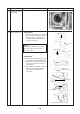
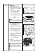
1. Detachment
1) Carry out work of item 1 of
.
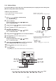
2) Remove connectors which are connected
from the control P.C. board to the other
parts and then remove wiring from the
clamp.
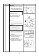
CN510 : Louver motor (20P, White)
CN34 : Float switch (3P, Red)
CN504 : Drain pump (2P, White)
CN101 : TC sensor (2P, Black)
CN102 : TCJ sensor (2P, Red)
CN104 : Room temp. Sensor (2P, Orange)
CN333 : Fan motor power supply
(5P, White)
CN334 : Fan motor position detection
(3P, White)
NOTE :
Unlock the lock of the housing part and then
remove the connector.
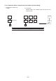
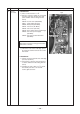
3) Unlock the locks of the card edge spacer
(6 positions) and then remove the control
P.C. board.
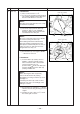
2. Attachment
1) Fix the control P.C. board to the card edge
spacer (6 positions)
2) Connect the connector removed in item 1
as before and then fix the wiring with the
clamp.
3) Following to work of item 2 of
, mount
the electric parts box cover and the
suction grille as before.
Remarks
Clamp
Card edge spacerCard edge spacer