
user manual

– 146 –
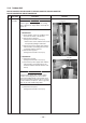
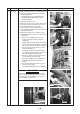
Valve fixing plate
Discharge port cabinetMotor base
Heat exchanger
Inverter assembly Side cabinet
Fin guard
Partition board
No.
Part name
Discharge
port cabinet
Procedure
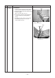
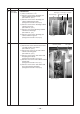
1. Detachment
1) Carry out work of 1 of
.
2) Remove screws for the discharge port
cabinet and the partition board.
(ST1T Ø4 × 8, 4 pcs.)
3) Remove screws for the discharge port
cabinet and the bottom plate.
(Hexagonal screw Ø4 × 10, 2 pcs.)
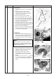
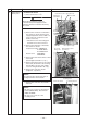
4) Remove screws for the discharge cabinet
and the motor base.
(ST1T Ø4 × 8, 2 pcs.)
5) Remove screw for the discharge cabinet
and the heat exchanger.
(ST1T Ø4 × 8, 1 pc.)
6) Remove screws for the discharge port
cabinet and the fin guard.
(Hexagonal screw Ø4 × 10, 2 pcs.)
Remarks
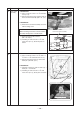
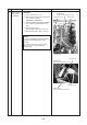
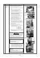
1) Carry out work of 1 of
.
2) Remove the screws which fix the inverter
assembly and the side cabinet.
(ST1T Ø4 × 8, 2 pcs.)
3) Remove the screws for the side cabinet
and the valve fixing plate.
(ST1T Ø4 × 8, 2 pcs.)
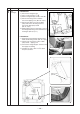
4) Remove screws for the side cabinet and
the piping panel (Rear).
(Hexagonal screw Ø4 × 10, 2 pcs.)
5) Remove screw for the side cabinet and the
bottom plate.
(Hexagonal screw Ø4 × 10, 1 pc.)
6) Remove screws for the side cabinet and
the fin guard (Heat exchanger).
(Hexagonal screw Ø4 × 10, 5 pcs.)
Side cabinet